Installation and Operator’s Manual |
|
|
| Page 13 of 63 | ||
|
| |||||
|
|
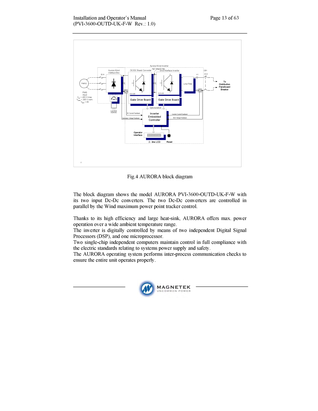
| Aurora Wind Inverter |
| ||
| Aurora Wind | DC/DC Boost Converter | High Voltage DC Bus |
|
| |
| Grid Interface Inverter | CB1 | ||||
| Inteface Box |
|
|
| K1 | 20 A |
| 20 A |
|
|
| ||
| PMSG |
|
|
| Line Filter | To |
|
|
|
| Distribution | ||
|
|
|
|
|
| Panelboard |
|
|
|
|
|
| Breaker |
| PMG | 3.6 kW |
| 3.6 kW |
|
|
| input |
|
|
| ||
|
|
|
|
|
| |
Voc | = 400 V max. | Gate Drive Board | Gate Drive Board |
| ||
Vnom | = 360 V nom. |
| ||||
| Vmin = 40 |
|
|
|
|
|
|
|
| Optoisolation |
|
| |
| Load Bank |
|
|
|
|
|
| (Optional) | DC Current Feedback | Inverter | Inverter Current Feedback |
| |
|
|
| ||||
|
|
|
| Inverter |
|
|
|
|
| Embedded |
|
| |
|
| Generator Voltage Feedback | Embedded | Grid Voltage Feedback |
| |
|
|
| Controller |
|
| |
|
|
| Controller |
|
| |
|
| Operator |
|
|
|
|
|
| Interface |
|
|
|
|
|
|
| 2 - line LCD | Reset |
| |