8 | Product Description | AXIS 250S User’s Manual |
Product Description
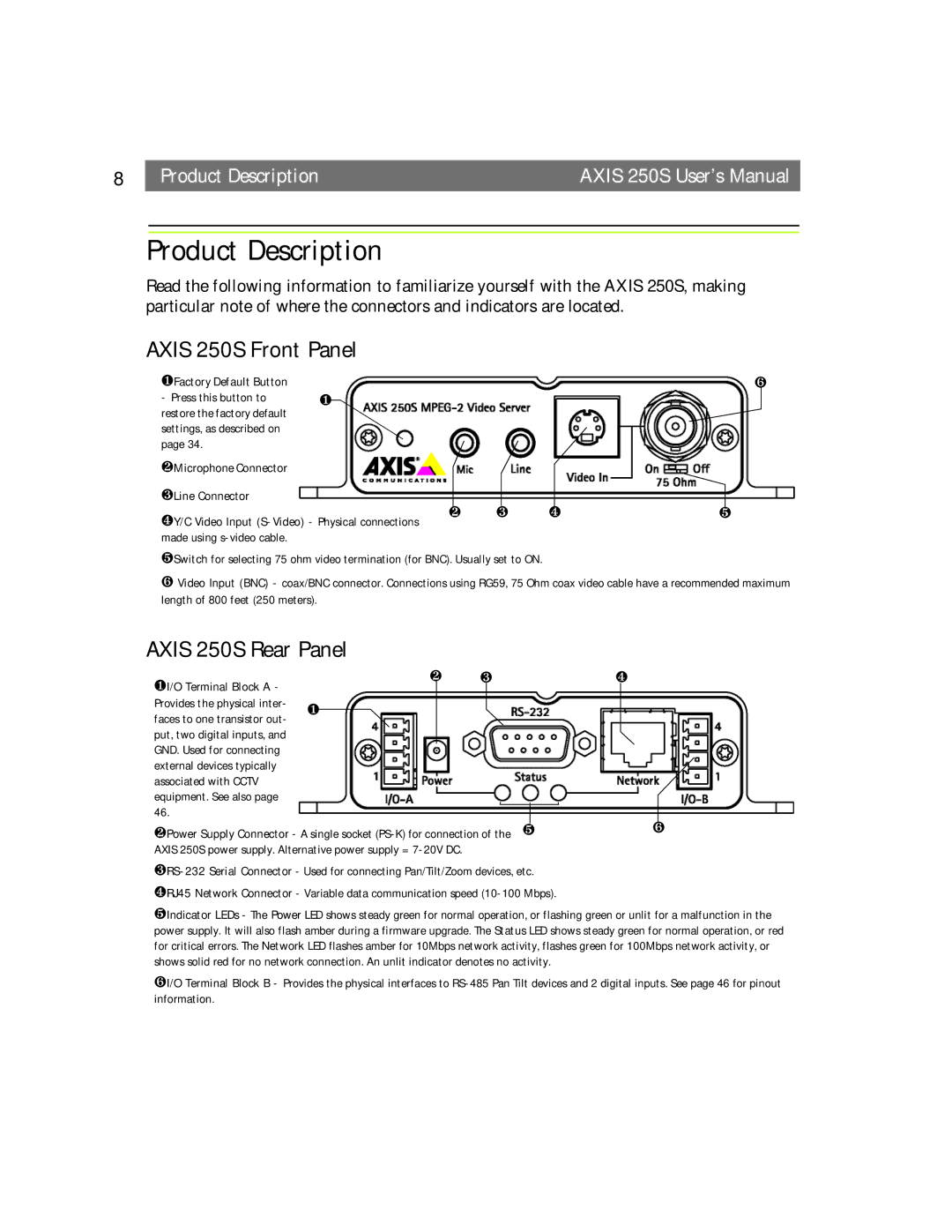
Read the following information to familiarize yourself with the AXIS 250S, making particular note of where the connectors and indicators are located.
AXIS 250S Front Panel
❶Factory Default Button | ❻ |
- Press this button to | ❶ |
restore the factory default |
|
settings, as described on |
|
page 34. |
|
❷Microphone Connector
❸Line Connector |
|
|
|
|
❹Y/C Video Input | ❷ | ❸ | ❹ | ❺ |
|
|
|
| |
made using |
|
|
|
|
❺Switch for selecting 75 ohm video termination (for BNC). Usually set to ON.
❻Video Input (BNC) - coax/BNC connector. Connections using RG59, 75 Ohm coax video cable have a recommended maximum length of 800 feet (250 meters).
AXIS 250S Rear Panel
❶I/O Terminal Block A - | ❷ | ❸ | ❹ | |||
|
|
|
|
|
| |
Provides the physical inter- | ❶ |
|
|
|
|
|
faces to one transistor out- |
|
|
|
|
|
|
put, two digital inputs, and |
|
|
|
|
|
|
GND. Used for connecting |
|
|
|
|
|
|
external devices typically |
|
|
|
|
|
|
associated with CCTV |
|
|
|
|
|
|
equipment. See also page |
|
|
|
|
|
|
46. |
|
|
|
|
| ❻ |
❷Power Supply Connector - A single socket | ||||||
AXIS 250S power supply. Alternative power supply = |
|
|
|
| ||
❹RJ45 Network Connector - Variable data communication speed
❺Indicator LEDs - The Power LED shows steady green for normal operation, or flashing green or unlit for a malfunction in the power supply. It will also flash amber during a firmware upgrade. The Status LED shows steady green for normal operation, or red for critical errors. The Network LED flashes amber for 10Mbps network activity, flashes green for 100Mbps network activity, or shows solid red for no network connection. An unlit indicator denotes no activity.
❻I/O Terminal Block B - Provides the physical interfaces to