AXIS 2130/2130R User’s Manual | The I/O Terminal Block Connector | 35 |
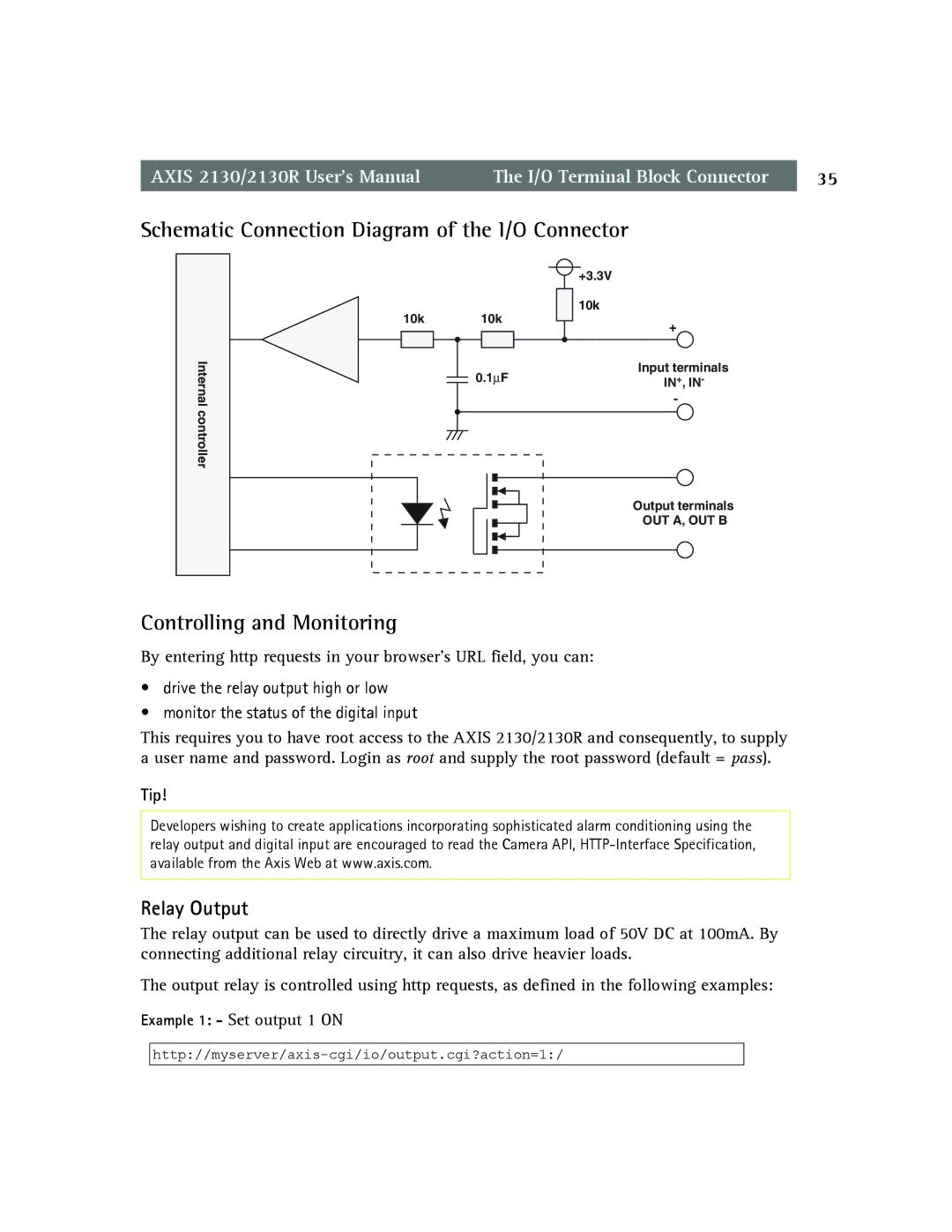
Schematic Connection Diagram of the I/O Connector
|
| +3.3V | |
10k | 10k | 10k | |
+ | |||
|
| ||
Internal | 0.1∝F | Input terminals | |
IN+, IN- | |||
| - | ||
controller |
|
| |
|
| Output terminals | |
|
| OUT A, OUT B |
Controlling and Monitoring
By entering http requests in your browser’s URL field, you can:
•drive the relay output high or low
•monitor the status of the digital input
This requires you to have root access to the AXIS 2130/2130R and consequently, to supply a user name and password. Login as root and supply the root password (default = pass).
Tip!
Developers wishing to create applications incorporating sophisticated alarm conditioning using the relay output and digital input are encouraged to read the Camera API,
Relay Output
The relay output can be used to directly drive a maximum load of 50V DC at 100mA. By connecting additional relay circuitry, it can also drive heavier loads.
The output relay is controlled using http requests, as defined in the following examples:
Example 1: - Set output 1 ON