A-channel line inputs
These accept balanced or unbalanced 1/4" jacks, tip = hot, ring = cold and sleeve = ground/screen.
Mic inputs
These are via
+Care should be taken not to plug microphones into the console (or stagebox / wallbox) while the phantom power is on. Also, mute the monitor / PA speaker when turning phantom power on or off. Allow one minute after powering up for the system to equilibrate before setting input gains.
Channel inserts
These porvide for unbalanced send and return from a single stereo jack socket. Wiring is: tip = out, ring = in and sleeve = ground/screen.
Direct outputs
This tap comes from just after the channel fader. Unbalanced 1/4" jacks.
B-channel inputs/tape returns
These also accept balanced or unbalanced 1/4" jacks and are switchable, in groups of eight, between
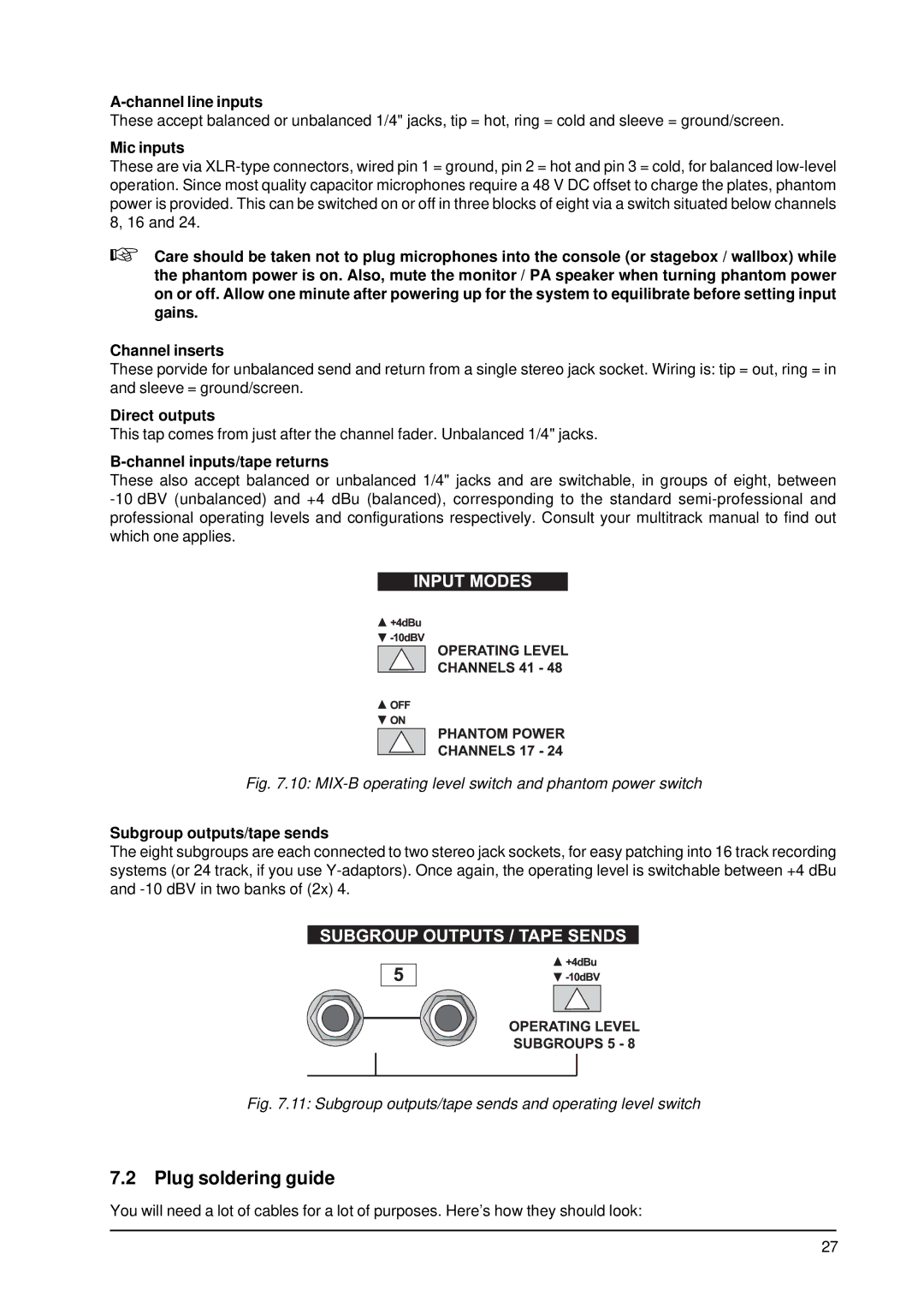
Fig. 7.10: MIX-B operating level switch and phantom power switch
Subgroup outputs/tape sends
The eight subgroups are each connected to two stereo jack sockets, for easy patching into 16 track recording systems (or 24 track, if you use
Fig. 7.11: Subgroup outputs/tape sends and operating level switch
7.2 Plug soldering guide
You will need a lot of cables for a lot of purposes. Here’s how they should look:
27