Manuals
/
Behringer
/
Computer Equipment
/
Electronic Accessory
Behringer
MX9000
user manual
Models:
MX9000
1
29
57
57
Download
57 pages
34.68 Kb
26
27
28
29
30
31
32
33
Specifications
Warranty
Dimension
INPUT/OUTPUT Configuration
Looming problems
Channel setting up procedure
Impedances and Tuning
Input gain setting
Headphones
Safety
Page 29
Image 29
29
Page 28
Page 30
Page 29
Image 29
Page 28
Page 30
Contents
EURODESKMX9000
Safety Instructions
Foreword
Table of Content
Track Recording with 2 Samplers
Eurodesk Overview
Manual
Metering
PSU Power Supply Unit
Channel strip
Input switching
INPUT/OUTPUT Channel
Channel input switching architecture
Input gain setting
Aux sends
Main equalizer
Aux sends
Routing and muting
Routing
Channel
B-channel
Inserts
Subgroups
Subgroup and Direct Outputs
Stereo subgroup channel schematic
Direct outputs
Master Panel
Aux masters
Aux sends
Aux returns
Stereo aux returns
Solo
MIX-B master
Aux returns 1
Monitoring
Monitoring
Phones
Headphones
1 PFL
Talkback
Expander port bus inputs
Connections
Rear panel
Auxiliary returns
Auxiliary sends
Track in/out
Subgroup inserts
Track/external inputs
Main inserts
Phones 1/2
Stereo outputs
Meter/analyzer out
Master balanced outputs
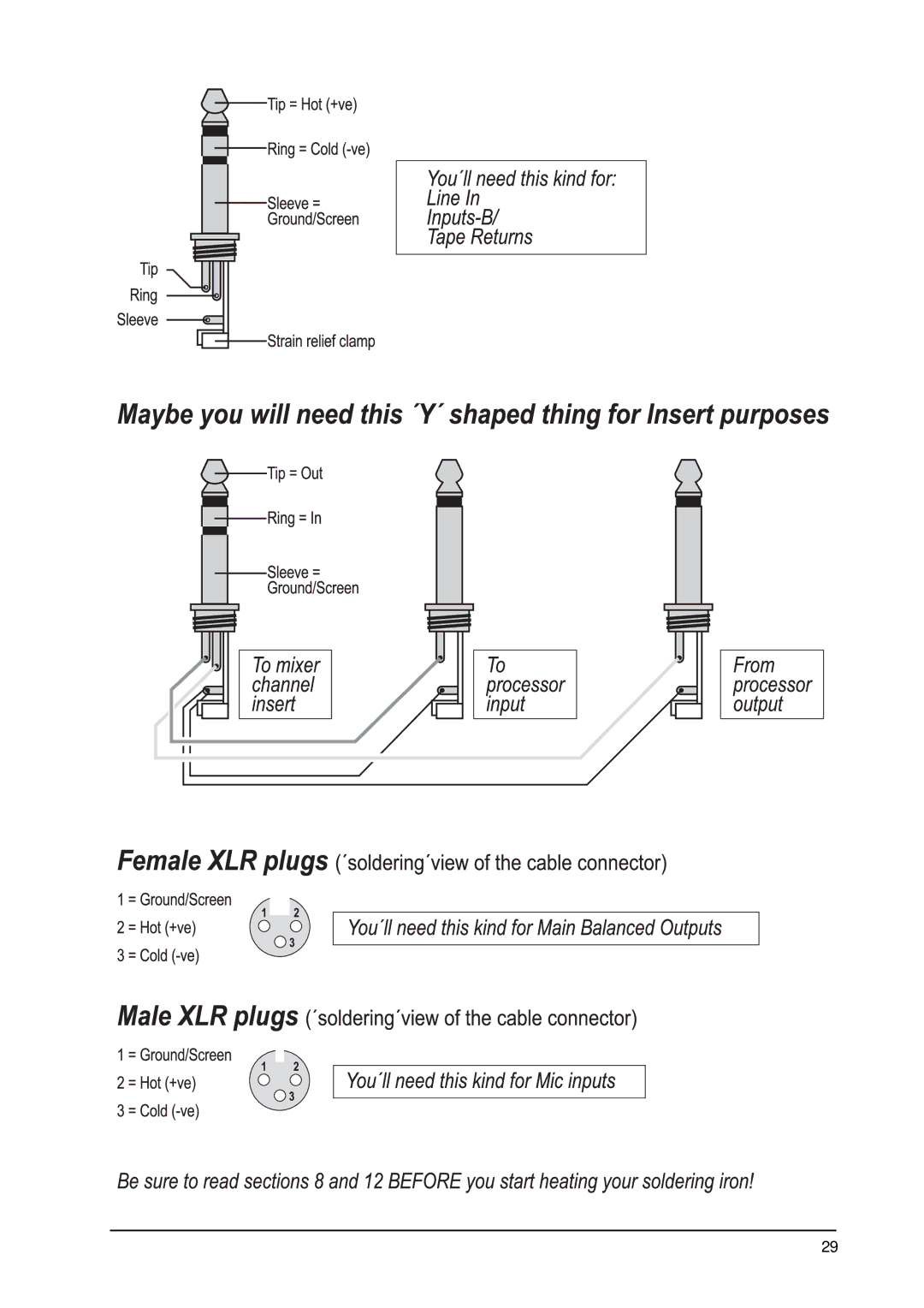
Plug soldering guide
Page
Page
Patchfield
Patchfield
Normalized bay
Example of patchbay configurations
Bay
Looming problems
Equalization
Gain Optimization
Unbalanced Lines
Impedances and Tuning
A balanced microphone line
START-UP
Channel setting up procedure
Desk/tape setting up procedures
Multitrack initialization
Track Midi SUITE/DANCE Production Studio
13.2.3Recording levels
13.2.4Auditioning a mix
Alternatively
Auxless headphones mix
Sends
Returns
Slightly more complicated auxless headphones mix
Lining up record/sample inputs
Track Recording with 2 Samplers
Mixdown
Recording
Professional 24-TRACK Studio
Headphones
Tab .1 Channel assignment
Very tricky headphones
Wet monitoring
FOH
Live P.A. with 2-TRACK Recording
Live Concert with 24-TRACK Recording
Tab .2 Front/rear/stage monitors routing
Timecode
Expanding the Eurodesk MX9000
Connections
Alignment
However
Bouncing
Sequencing Live
Modifications
INPUT/OUTPUT Configuration
LED meters pre fader
Aux sends post EQ
MIX-B source post fader
Specifications
General
Power supply
Dimensions/weight
§ 1 Warranty CARD/ONLINE Registration
Warranty
Page
Top
Page
Image
Contents