11. IMPEDANCES AND TUNING
Electronic inputs tend to have impedances measured in tens of kiloOhms. Outputs, on the other hand, are generally two or three orders of magnitude less. This is just as well, otherwise a signal at an output might find that the line of least resistance is the limit of the preceding unit.
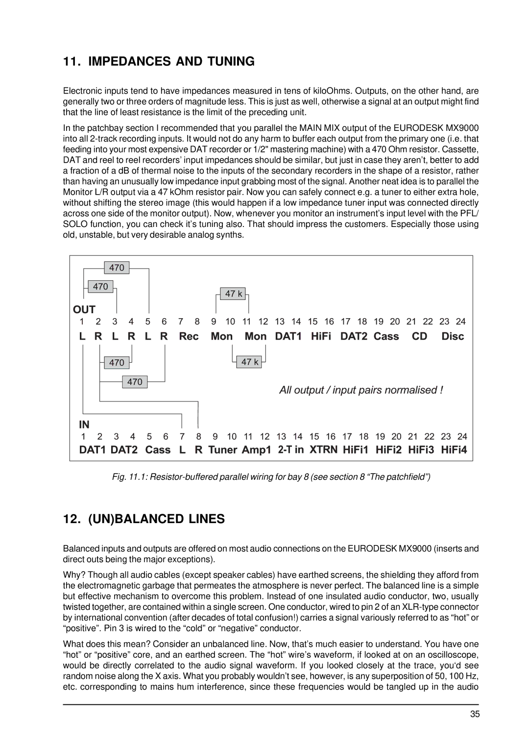
In the patchbay section I recommended that you parallel the MAIN MIX output of the EURODESK MX9000 into all
Fig. 11.1: Resistor-buffered parallel wiring for bay 8 (see section 8 “The patchfield”)
12. (UN)BALANCED LINES
Balanced inputs and outputs are offered on most audio connections on the EURODESK MX9000 (inserts and direct outs being the major exceptions).
Why? Though all audio cables (except speaker cables) have earthed screens, the shielding they afford from the electromagnetic garbage that permeates the atmosphere is never perfect. The balanced line is a simple but effective mechanism to overcome this problem. Instead of one insulated audio conductor, two, usually twisted together, are contained within a single screen. One conductor, wired to pin 2 of an
What does this mean? Consider an unbalanced line. Now, that’s much easier to understand. You have one “hot” or “positive” core, and an earthed screen. The “hot” wire’s waveform, if looked at on an oscilloscope, would be directly correlated to the audio signal waveform. If you looked closely at the trace, you‘d see random noise along the X axis. What you probably wouldn’t see, however, is any superposition of 50, 100 Hz, etc. corresponding to mains hum interference, since these frequencies would be tangled up in the audio
35