RS-232↔IEEE 488 INTERFACE CONVERTER
DB9 Female | DB25 Male | |||||||
DCD | 1 |
|
|
|
|
|
|
|
|
|
|
|
|
| |||
2 |
|
|
|
|
| 3 | ||
|
|
|
| |||||
3 |
|
|
|
|
| 2 | ||
|
|
|
| |||||
DTR | 4 |
|
|
|
|
|
|
|
|
|
|
|
|
| |||
Gnd | 5 |
|
|
|
|
| 7 | Gnd |
|
|
|
| |||||
DSR | 6 |
|
|
|
|
|
|
|
|
|
|
|
|
| |||
RTS | 7 |
|
|
|
|
| 4 | CTS |
|
|
|
| |||||
CTS | 8 |
|
|
|
| 5 | RTS | |
|
|
|
| |||||
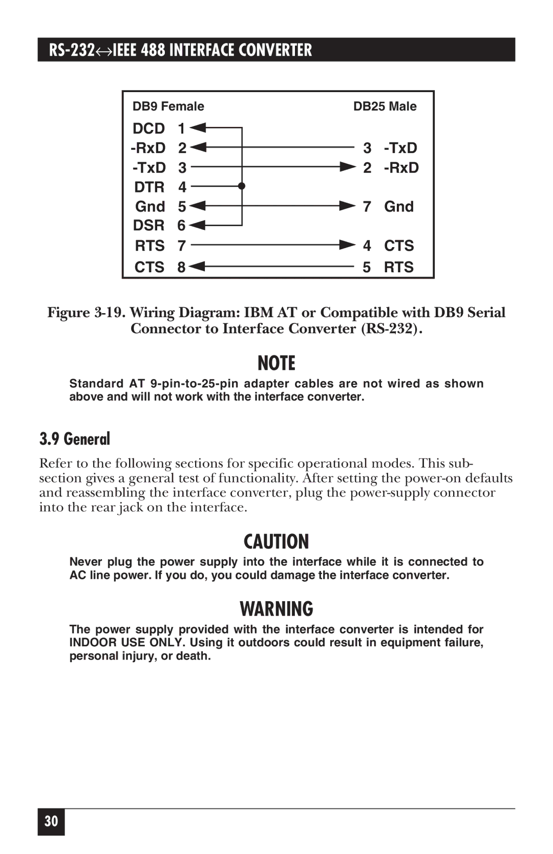
Figure 3-19. Wiring Diagram: IBM AT or Compatible with DB9 Serial
Connector to Interface Converter (RS-232).
NOTE
Standard AT
3.9 General
Refer to the following sections for specific operational modes. This sub- section gives a general test of functionality. After setting the
CAUTION
Never plug the power supply into the interface while it is connected to AC line power. If you do, you could damage the interface converter.
WARNING
The power supply provided with the interface converter is intended for INDOOR USE ONLY. Using it outdoors could result in equipment failure, personal injury, or death.
30
