RS-232↔IEEE 488 INTERFACE CONVERTER
7.Theory of Operation and Board Layout
7.1Theory of Operation
The heart of the interface converter is a 6809 microprocessor (U101) supported by 8K bytes of firmware EPROM [U102 (2764)] and 32K bytes of static RAM [U103 (58256)]. A Versatile Interface Adapter [U104 (65B22)] is used to generate
The
The internal DIP switches [SW1, SW2, and SW3] are read via 74HCT244
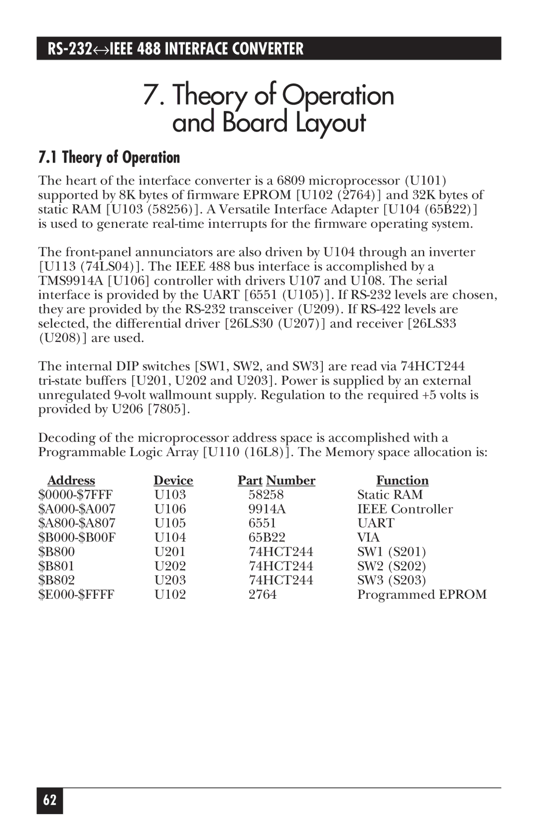
Decoding of the microprocessor address space is accomplished with a Programmable Logic Array [U110 (16L8)]. The Memory space allocation is:
Address | Device | Part Number | Function |
U103 | 58258 | Static RAM | |
U106 | 9914A | IEEE Controller | |
U105 | 6551 | UART | |
U104 | 65B22 | VIA | |
$B800 | U201 | 74HCT244 | SW1 (S201) |
$B801 | U202 | 74HCT244 | SW2 (S202) |
$B802 | U203 | 74HCT244 | SW3 (S203) |
U102 | 2764 | Programmed EPROM |
62
