Digital Video Recorder 440/480 SeriesHardware setup en 21
4 | Hardware setup |
| This chapter contains detailed information about the hardware installation and connection of |
| external equipment to the unit. The connector types and their pin signals are described. Most |
| of the connectors are located at the rear panel of the unit. For convenience, one USB port is |
| located on the front of the unit to connect a mouse or memory device. |
| All the input/output ports are Safety Extra Low Voltage (SELV) circuits. SELV circuits should |
| only be connected to other SELV circuits. |
4.1 | Camera connections |
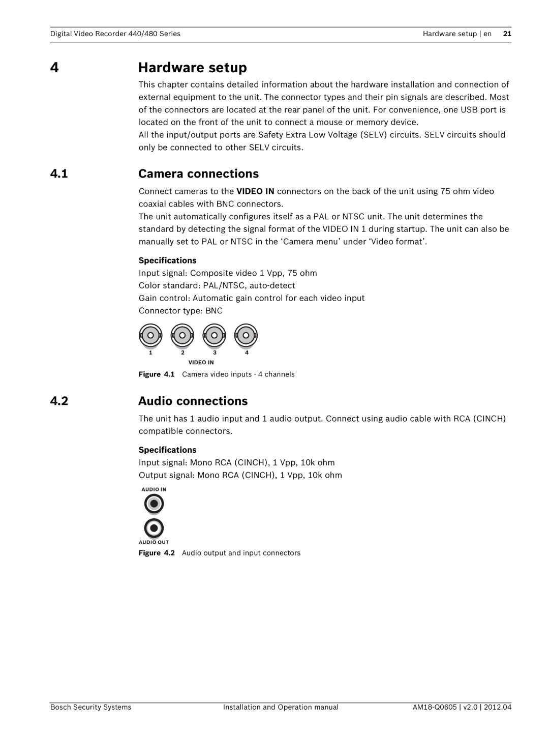
| Connect cameras to the VIDEO IN connectors on the back of the unit using 75 ohm video |
| coaxial cables with BNC connectors. |
| The unit automatically configures itself as a PAL or NTSC unit. The unit determines the |
standard by detecting the signal format of the VIDEO IN 1 during startup. The unit can also be manually set to PAL or NTSC in the ‘Camera menu’ under ‘Video format’.
Specifications
Input signal: Composite video 1 Vpp, 75 ohm
Color standard: PAL/NTSC,
Gain control: Automatic gain control for each video input
Connector type: BNC
| Figure 4.1 Camera video inputs - 4 channels |
4.2 | Audio connections |
| The unit has 1 audio input and 1 audio output. Connect using audio cable with RCA (CINCH) |
| compatible connectors. |
Specifications
Input signal: Mono RCA (CINCH), 1 Vpp, 10k ohm
Output signal: Mono RCA (CINCH), 1 Vpp, 10k ohm
Figure 4.2 Audio output and input connectors
Bosch Security Systems | Installation and Operation manual |
|
