16 en Quick installDigital Video Recorder 440/480 Series
3 | Quick install | ||||||||||||||||
| To get the unit quickly operational, make the connections described below and then enter the | ||||||||||||||||
| relevant data in the Quick install menu. The Quick install menu appears the first time the unit | ||||||||||||||||
| is started. | ||||||||||||||||
3.1 | Connections | ||||||||||||||||
|
|
|
|
|
|
|
|
|
|
|
|
|
|
|
|
|
|
|
|
|
|
|
|
|
|
|
|
|
|
|
|
|
|
|
|
|
|
|
|
|
|
|
|
|
|
|
|
|
|
|
|
|
|
|
|
|
|
|
|
|
|
|
|
|
|
|
|
|
|
|
|
|
|
|
|
|
|
|
|
|
|
|
|
|
|
|
|
|
|
|
|
|
|
|
|
|
|
|
|
|
|
|
|
|
|
|
|
|
|
|
|
|
|
|
|
|
|
|
|
|
|
|
|
|
|
|
|
|
|
|
|
|
|
|
|
|
|
|
|
|
|
|
|
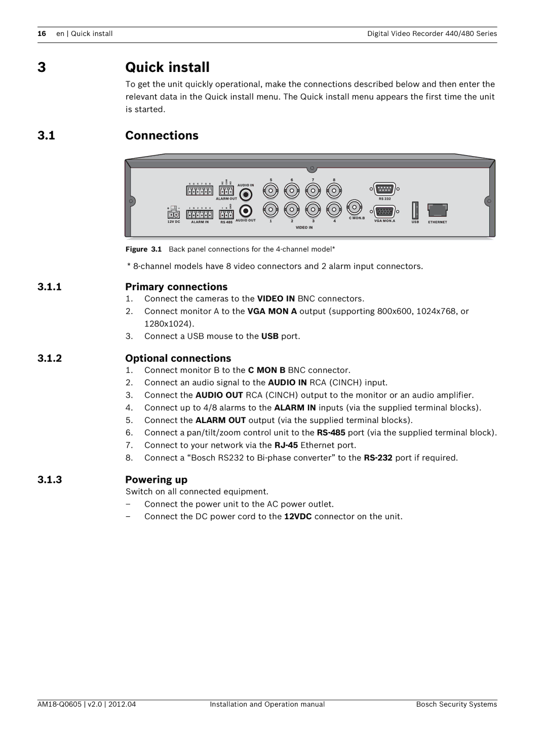
Figure 3.1 Back panel connections for the 4-channel model*
*
3.1.1 | Primary connections | |
| 1. | Connect the cameras to the VIDEO IN BNC connectors. |
| 2. | Connect monitor A to the VGA MON A output (supporting 800x600, 1024x768, or |
|
| 1280x1024). |
| 3. | Connect a USB mouse to the USB port. |
3.1.2 | Optional connections | |
| 1. | Connect monitor B to the C MON B BNC connector. |
| 2. | Connect an audio signal to the AUDIO IN RCA (CINCH) input. |
| 3. | Connect the AUDIO OUT RCA (CINCH) output to the monitor or an audio amplifier. |
| 4. | Connect up to 4/8 alarms to the ALARM IN inputs (via the supplied terminal blocks). |
| 5. | Connect the ALARM OUT output (via the supplied terminal blocks). |
| 6. | Connect a pan/tilt/zoom control unit to the |
| 7. | Connect to your network via the |
| 8. | Connect a “Bosch RS232 to |
3.1.3 | Powering up | |
| Switch on all connected equipment. | |
| – | Connect the power unit to the AC power outlet. |
| – | Connect the DC power cord to the 12VDC connector on the unit. |
Installation and Operation manual | Bosch Security Systems |
