![]() BM 2610027879
BM 2610027879
Adjustments
Using the Head Assembly lock pin
!WARNING To avoid possible injury, disconnect plug from power
source before performing any assembly, adjustments or repairs.
Head Assembly lock pin
The head assembly lock pin (item 43 - page 9) is located on the right side of the pivot post (item 34 - page 9). It is used to hold the saw’s head assembly in the DOWN position. This position prevents the head from bouncing up and down during transportation. This also makes the saw more compact for lifting and storage. This position is also required for some calibrating procedures.
To Engage the Head Assembly lock pin
1.Check that the depth stop plate (item 33 - page 9) is disengaged, or pressed in to the left position.
2.Grasp the saw’s main handle (item 3 - page 8) and press down on the head assembly.
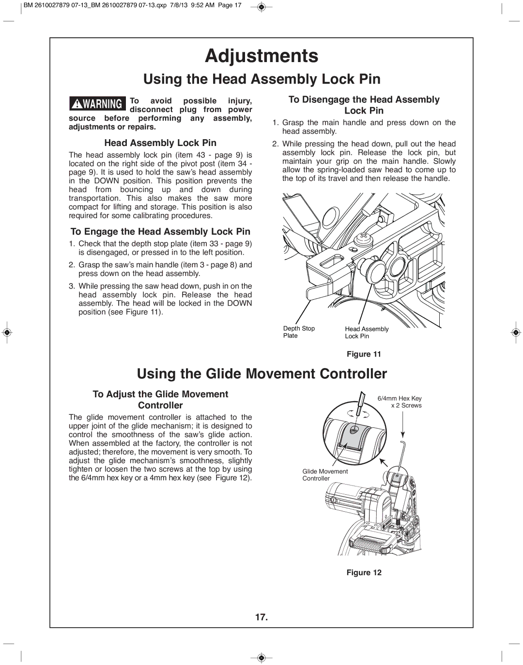
3.While pressing the saw head down, push in on the head assembly lock pin. Release the head assembly. The head will be locked in the DOWN position (see Figure 11).
To Disengage the Head Assembly
lock pin
1.Grasp the main handle and press down on the head assembly.
2.While pressing the head down, pull out the head assembly lock pin. Release the lock pin, but maintain your grip on the main handle. Slowly allow the
|
|
|
|
|
|
|
|
|
|
|
|
|
|
|
|
|
|
|
|
|
|
|
|
|
|
|
|
|
|
|
|
|
|
|
|
|
|
|
|
|
|
|
|
|
|
|
|
|
|
|
|
|
|
|
|
|
|
|
|
|
|
|
|
|
|
|
|
|
|
|
|
|
|
|
|
|
|
|
|
|
|
|
|
|
|
|
|
|
|
|
|
|
|
|
|
|
|
|
|
|
|
|
|
|
|
|
|
|
|
|
|
|
|
|
|
|
|
|
|
|
|
|
|
|
|
|
|
|
|
|
|
|
|
|
|
|
|
|
|
|
|
|
|
|
|
|
|
|
|
|
|
|
|
|
|
|
|
|
|
|
|
|
|
|
|
|
|
|
|
|
|
|
|
|
|
|
|
|
|
|
|
|
|
|
|
|
|
|
|
|
|
|
|
|
|
|
|
|
|
|
|
|
|
|
|
|
|
|
|
|
|
|
|
|
|
|
|
|
|
|
|
|
|
|
|
|
|
|
|
|
|
|
|
|
|
|
|
|
|
|
|
|
|
|
|
|
|
|
|
|
|
|
|
|
|
|
|
|
|
|
|
|
|
|
|
|
|
|
|
|
|
|
|
|
|
|
|
|
|
|
|
|
|
|
|
|
|
|
|
|
|
|
|
|
|
|
|
|
|
|
|
|
|
|
|
|
|
|
|
|
|
Depth Stop |
|
|
| Head Assembly |
|
|
| |||||||||||||||||||||||||||||||
|
|
|
|
| ||||||||||||||||||||||||||||||||||
|
|
|
| |||||||||||||||||||||||||||||||||||
Plate |
|
|
| Lock Pin | ||||||||||||||||||||||||||||||||||
figure 11
Using the Glide Movement Controller
To Adjust the Glide Movement
Controller
The glide movement controller is attached to the upper joint of the glide mechanism; it is designed to control the smoothness of the saw’s glide action. When assembled at the factory, the controller is not adjusted; therefore, the movement is very smooth. To adjust the glide mechanism’s smoothness, slightly tighten or loosen the two screws at the top by using the 6/4mm hex key or a 4mm hex key (see Figure 12).
6/4mm Hex Key x 2 Screws
Glide Movement
Controller
figure 12
17.