![]() BM 2610027879
BM 2610027879
Getting To Know Your Miter Saw
7 ![]()
![]() 1
1
44
(not shown) 32
42 | 34 |
33 | 35 |
| |
43 | 36 |
| 37 |
| 38 |
4140
39
(not shown)
45
(not shown)
22
46
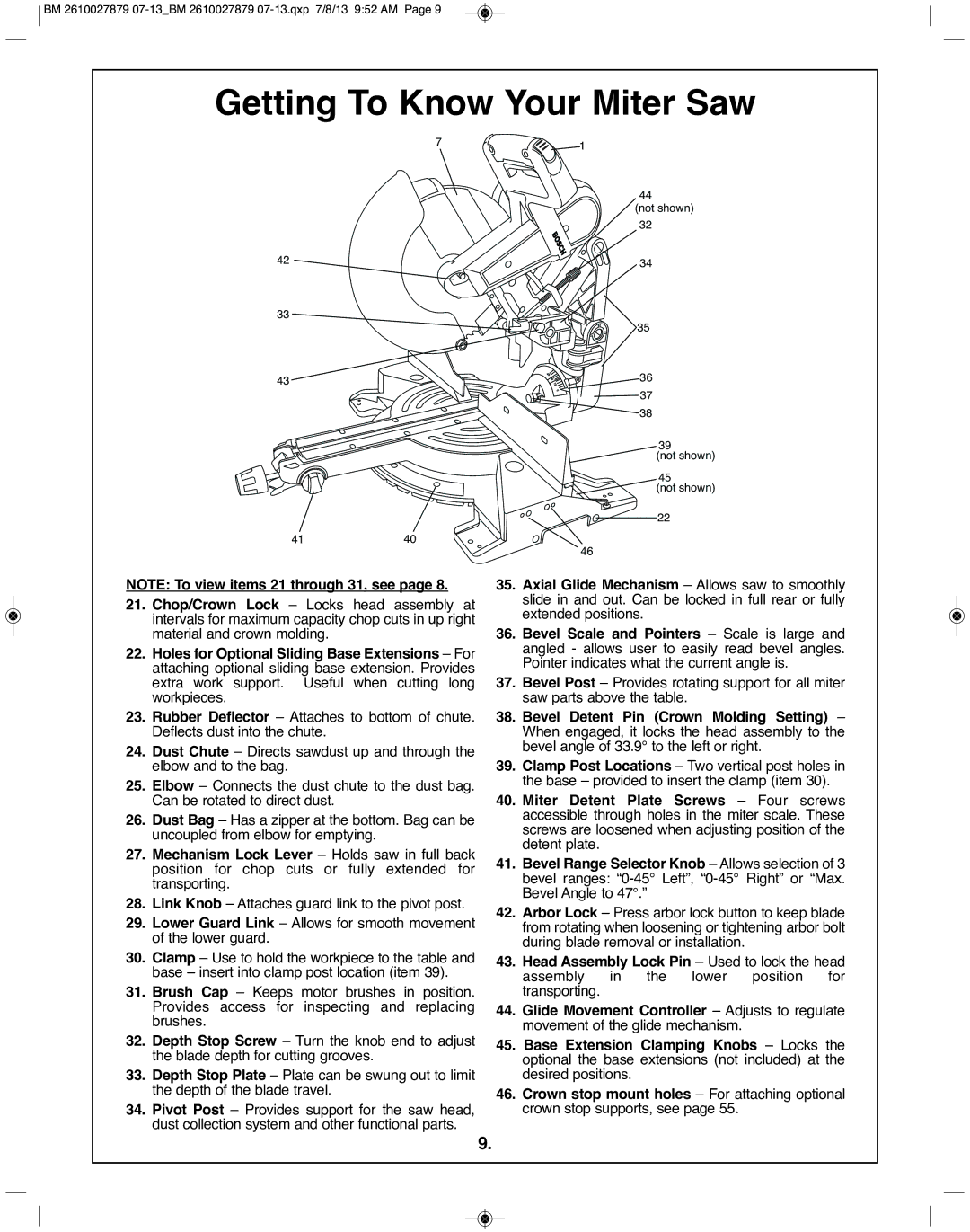
NOTE: To view items 21 through 31, see page 8.
21.Chop/Crown lock – Locks head assembly at intervals for maximum capacity chop cuts in up right material and crown molding.
22.Holes for Optional Sliding Base Extensions – For attaching optional sliding base extension. Provides extra work support. Useful when cutting long workpieces.
23.Rubber Deflector – Attaches to bottom of chute. Deflects dust into the chute.
24.Dust Chute – Directs sawdust up and through the elbow and to the bag.
25.Elbow – Connects the dust chute to the dust bag. Can be rotated to direct dust.
26.Dust Bag – Has a zipper at the bottom. Bag can be uncoupled from elbow for emptying.
27.Mechanism lock lever – Holds saw in full back position for chop cuts or fully extended for transporting.
28.link Knob – Attaches guard link to the pivot post.
29.lower Guard link – Allows for smooth movement of the lower guard.
30.Clamp – Use to hold the workpiece to the table and base – insert into clamp post location (item 39).
31.Brush Cap – Keeps motor brushes in position. Provides access for inspecting and replacing brushes.
32.Depth Stop Screw – Turn the knob end to adjust the blade depth for cutting grooves.
33.Depth Stop plate – Plate can be swung out to limit the depth of the blade travel.
34.pivot post – Provides support for the saw head, dust collection system and other functional parts.
35.Axial Glide Mechanism – Allows saw to smoothly slide in and out. Can be locked in full rear or fully extended positions.
36.Bevel Scale and pointers – Scale is large and angled - allows user to easily read bevel angles. Pointer indicates what the current angle is.
37.Bevel post – Provides rotating support for all miter saw parts above the table.
38.Bevel Detent pin (Crown Molding Setting) – When engaged, it locks the head assembly to the bevel angle of 33.9° to the left or right.
39.Clamp post locations – Two vertical post holes in the base – provided to insert the clamp (item 30).
40.Miter Detent plate Screws – Four screws accessible through holes in the miter scale. These screws are loosened when adjusting position of the detent plate.
41.Bevel Range Selector Knob – Allows selection of 3 bevel ranges:
42.Arbor lock – Press arbor lock button to keep blade from rotating when loosening or tightening arbor bolt during blade removal or installation.
43.Head Assembly lock pin – Used to lock the head assembly in the lower position for transporting.
44.Glide Movement Controller – Adjusts to regulate movement of the glide mechanism.
45.Base Extension Clamping Knobs – Locks the optional the base extensions (not included) at the desired positions.
46.Crown stop mount holes – For attaching optional crown stop supports, see page 55.
9.