6H122-08 specifications
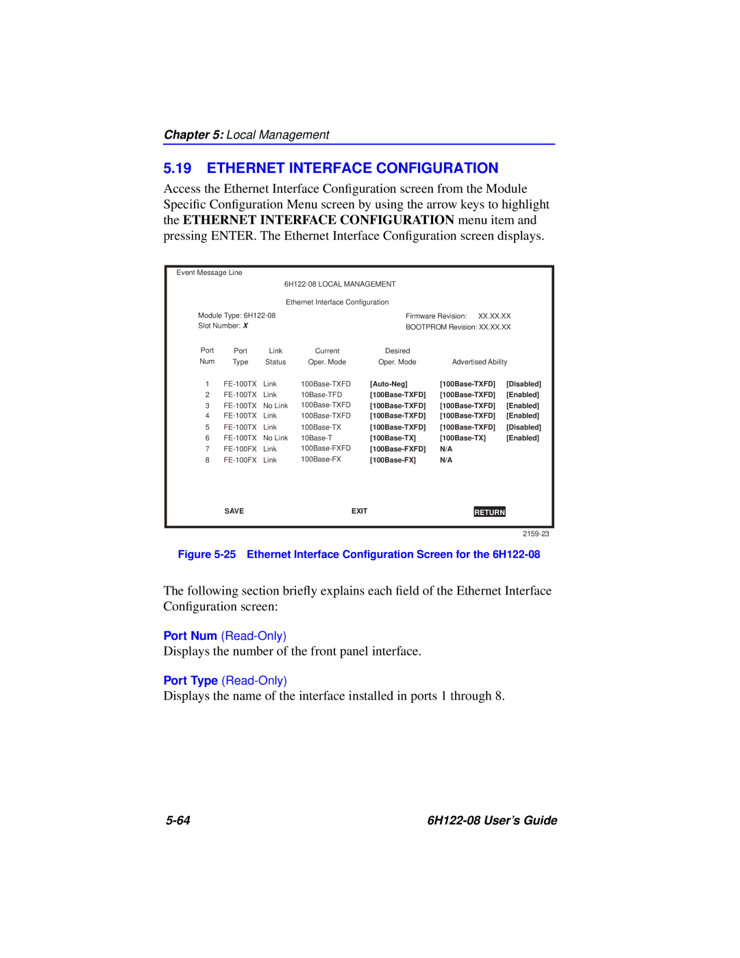
Cabletron Systems 6H122-08 is a robust multi-port network switch designed for efficient data transfer and connectivity in both enterprise and industrial networking scenarios. Known for its reliability, Cabletron has established a reputation for producing high-performance network hardware that meets the demands of modern network traffic.One of the key features of the 6H122-08 is its capability to handle various Ethernet technologies, including 10Base-T, 100Base-TX, and 100Base-FX, ensuring compatibility with a wide range of devices and networks. Supporting both wired and optical connections allows for flexible deployment options, catering to varying infrastructure needs. The switch is equipped with multiple 10/100 Mbps ports, enabling seamless communication between devices in local area networks.
The architecture of the Cabletron 6H122-08 relies on a high-performance switching fabric that minimizes latency and ensures efficient packet forwarding. This is particularly important in environments where real-time data transfer is critical, such as video conferencing, online gaming, and VoIP applications. The switch’s capability to manage data traffic effectively helps in reducing network congestion, thereby enhancing overall performance.
In terms of security, the Cabletron 6H122-08 incorporates access control features, allowing network administrators to set permissions for various users and devices. This ensures that sensitive data is only accessible to authorized personnel, bolstering the network’s security posture. Additionally, the switch supports VLANs (Virtual Local Area Networks), which help in segmenting network traffic and improving performance by isolating different groups of users or applications.
The management of the 6H122-08 can be done through a user-friendly interface, which provides comprehensive monitoring and troubleshooting tools. This feature simplifies network management and allows IT professionals to quickly diagnose and resolve issues, ensuring minimal downtime.
Moreover, the Cabletron Systems 6H122-08 is built with durability in mind. Its rugged design makes it suitable for deployment in environments with varying temperature conditions and physical demands, thereby ensuring longevity and consistent performance.
In conclusion, the Cabletron Systems 6H122-08 stands out in the realm of networking solutions due to its versatility, performance, and security features. With support for multiple Ethernet standards, effective traffic management, and robust security protocols, it meets the diverse needs of businesses and organizations investing in reliable, high-speed network infrastructures.

