Synchronizing the Camcorder’s Time Code
You can synchronize this camcorder’s time code to an external time code generator. You can also include in the recording the user bit signal received from the TIME CODE terminal (![]() 48). The camcorder offers the following synchronization options.
48). The camcorder offers the following synchronization options.
Genlock
When a reference sync signal (analog blackburst or
Time Code IN
Set the TIME CODE switch to IN to start the Time Code IN mode. An external
Time Code OUT
Set the TIME CODE switch to OUT to start the Time Code OUT mode. The camcorder’s internal time code is sent out from the TIME CODE terminal as a standard LTC timing signal.
When [SIGNAL SETUP] ![]()
![]() [SDI OUTPUT] is set to [ON(OSD)] or [ON], the time code signal will be output also through the HD/SD SDI terminal.
[SDI OUTPUT] is set to [ON(OSD)] or [ON], the time code signal will be output also through the HD/SD SDI terminal.
When [SIGNAL SETUP] ![]()
![]() [UB OUT] is set to [HD 24P 2:3], the user bit of the time code signal will be 2:3 pulldown data (when recording in 24F mode or playing back movies that are HDV 1080/24p). In other words, when recording in 24F mode or playing back movies that are HDV 1080/24p, the signal is converted to 60i using the 2:3 pulldown method and output from the HD/SD SDI terminal. An external device can receive the data used in this conversion (2:3 pulldown data) to convert the signal to 1080/24p specifications.
[UB OUT] is set to [HD 24P 2:3], the user bit of the time code signal will be 2:3 pulldown data (when recording in 24F mode or playing back movies that are HDV 1080/24p). In other words, when recording in 24F mode or playing back movies that are HDV 1080/24p, the signal is converted to 60i using the 2:3 pulldown method and output from the HD/SD SDI terminal. An external device can receive the data used in this conversion (2:3 pulldown data) to convert the signal to 1080/24p specifications.
![]() *
*
Genlock |
| – |
| – |
Time Code/User bit IN |
| – | – | – |
|
|
|
|
|
Time Code OUT |
|
| – | – |
|
|
|
|
|
*In SD mode, Time Code IN is not available if you select the 24F frame rate (the mode will be canceled and the
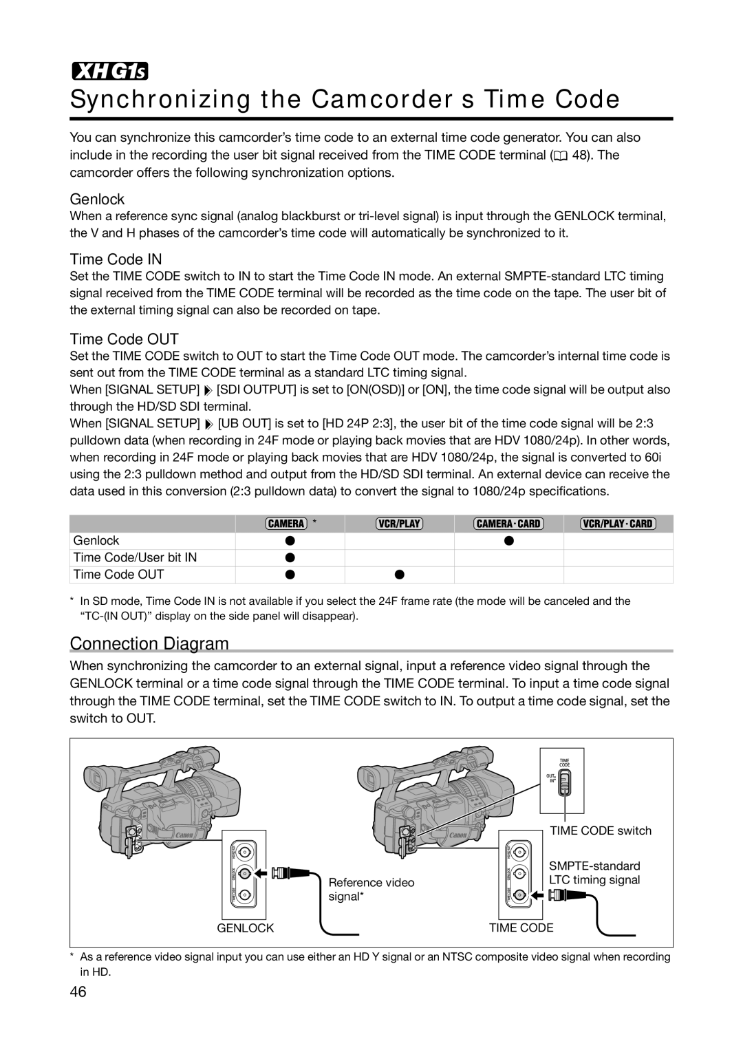
Connection Diagram
When synchronizing the camcorder to an external signal, input a reference video signal through the GENLOCK terminal or a time code signal through the TIME CODE terminal. To input a time code signal through the TIME CODE terminal, set the TIME CODE switch to IN. To output a time code signal, set the switch to OUT.
| TIME CODE switch |
| |
Reference video | LTC timing signal |
signal* |
|
GENLOCK | TIME CODE |
*As a reference video signal input you can use either an HD Y signal or an NTSC composite video signal when recording in HD.
46