Table 1 — 50VQP Unit Physical Data
UNIT 50VQP | 084 |
| 096 |
| 120 | 150 |
| 168 |
| 192 |
| 240 | 300 |
COMPRESSOR QUANTITY |
|
| Scroll (1) |
|
|
|
| Scroll (2) |
| ||||
Factory Charge | 3.97 |
| 4.42 |
| 6.35 | 7.03 |
| 3.97 |
| 4.42 |
| 6.35 | 7.03 |
BLOWER MOTOR |
|
|
|
|
|
|
|
|
|
|
|
|
|
Blower Motor Quantity |
|
|
|
|
|
| 1 |
|
|
|
|
| |
Standard Motor (kW) | .75 |
| 1.12 |
| 1.49 | 2.24 |
| 1.49 |
| 2.24 |
| 3.73 | 3.73 |
Large Motor (kW) | 1.12 |
| 1.49 |
| 2.24 | 3.73 |
| 2.24 |
| 3.73 |
| 5.60 | 5.60 |
BLOWER |
|
|
|
|
|
|
|
|
|
|
|
|
|
No. of Blowers |
|
| 1 |
|
|
|
|
| 2 |
|
| ||
Blower Wheel Size D x W (cm) |
| 38.1 x 27.9 |
| 38.1 x |
|
| 38.1 x 27.9 |
| 38.1 x | ||||
|
| 38.1 |
|
|
| 38.1 | |||||||
|
|
|
|
|
|
|
|
|
|
|
| ||
WATER CONNECTION SIZE |
|
|
|
|
|
|
|
|
|
|
|
|
|
FPT (in.) [mm] |
|
|
| 2 [50.8] |
|
| |||||||
|
|
|
|
| [63.5] | ||||||||
|
|
|
|
|
|
|
|
|
|
|
|
| |
COAX VOLUME |
|
|
|
|
|
|
|
|
|
|
|
|
|
Volume (liters) | 8.28 |
|
| 9.37 | 13.11 |
| 18.29 |
|
| 24.08 | 27.98 | ||
CONDENSATE CONNECTION SIZE |
|
|
|
|
|
|
|
|
|
|
|
|
|
FPT (in.) [mm] |
|
|
|
|
| 1 [25.4] |
|
|
|
|
| ||
AIR COIL DATA |
|
|
|
|
|
|
|
|
|
|
|
|
|
Air Coil Dimensions H x W (cm) |
|
| 91.4 x 121.9 |
|
|
|
| 91.4 x 121.9 |
| ||||
Air Coil Total Face Area (sq m) |
|
| 1.11 |
|
|
|
|
| 2.22 |
|
| ||
Air Coil Tube Size (cm) |
|
|
|
|
| 3/8 [0.953] |
|
|
|
|
| ||
Air Coil Fin Spacing (fins per cm) |
|
| 5.5 |
|
| 4.72 |
|
|
| 5.5 |
|
| 4.72 |
Air Coil Number of Rows | 2 |
|
| 3 | 4 |
| 2 |
|
| 3 | 4 | ||
MISCELLANEOUS DATA |
|
|
|
|
|
|
|
|
|
|
|
|
|
Filter Standard Throwaway (qty) (cm) |
| (4) 45.74 x 63.5 x 2.5 |
|
|
| (8) 45.74 x 63.5 x 2.5 |
| ||||||
Weight - Operating (kg) | 399 |
|
| 422 | 435 |
| 725 |
|
| 755 | 769 | ||
Weight - Packaged (kg) | 406 |
|
| 429 | 442 |
| 739 |
|
| 769 | 782 | ||
LEGEND
FPT — Female Pipe Thread
NOTES:
1.All units have grommet and spring compressor mountings, and 2.2 cm and 3.5 cm electrical knockouts.
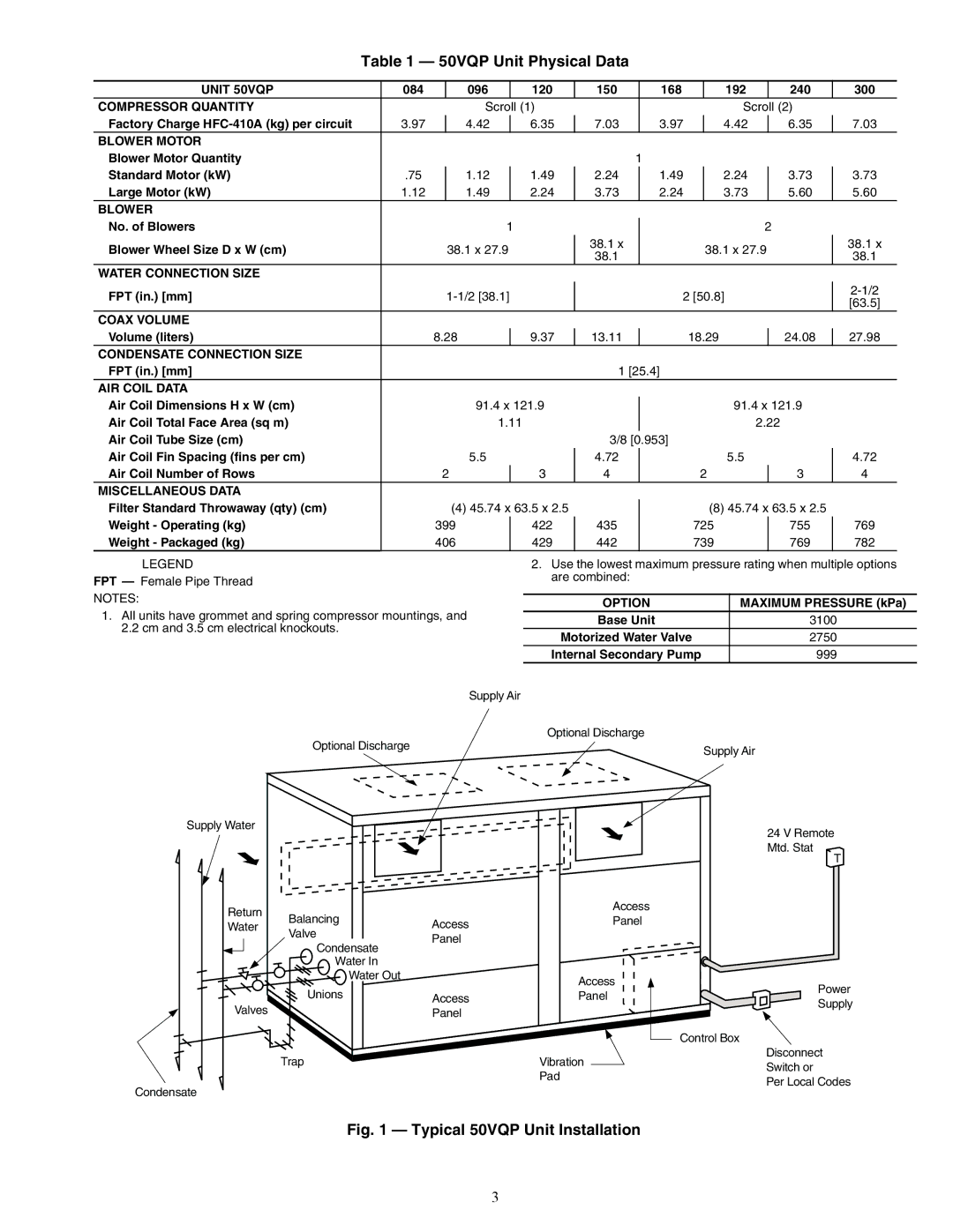
Supply Air
Optional Discharge
2.Use the lowest maximum pressure rating when multiple options are combined:
OPTION | MAXIMUM PRESSURE (kPa) |
Base Unit | 3100 |
Motorized Water Valve | 2750 |
Internal Secondary Pump | 999 |
Optional Discharge
Supply Air
Supply Water
Return | Balancing | Access | |
Water | |||
Valve | |||
| Panel | ||
| Condensate | ||
|
| ||
| Water In |
| |
| Water Out |
| |
| Unions | Access | |
Valves |
| ||
| Panel |
Trap
Condensate
Access
Panel
Access
Panel
Vibration
Pad
24 V Remote
Mtd. Stat
T
Power
Supply
Control Box
Disconnect Switch or
Per Local Codes
Fig. 1 — Typical 50VQP Unit Installation
3