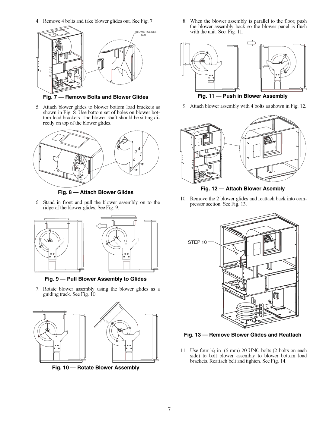
4. Remove 4 bolts and take blower glides out. See Fig. 7.
| BLOWER GLIDES |
| (2X) |
Fig. 7 — Remove Bolts and Blower Glides
5.Attach blower glides to blower bottom load brackets as shown in Fig. 8. Use bottom set of holes on blower bot- tom load brackets. The blower shaft should be sitting di- rectly on top of the blower glides.
a50-8470
Fig. 8 — Attach Blower Glides
6.Stand in front and pull the blower assembly on to the ridge of the blower glides. See Fig. 9.
|
Fig. 9 — Pull Blower Assembly to Glides
7.Rotate blower assembly using the blower glides as a guiding track. See Fig. 10.
|
Fig. 10 — Rotate Blower Assembly
8.When the blower assembly is parallel to the floor, push the blower assembly back so the blower panel is flush with the unit. See. Fig. 11.
a50-8473
Fig. 11 — Push in Blower Assembly
9.Attach blower assembly with 4 bolts as shown in Fig. 12.
Fig. 12 — Attach Blower Asembly
10.Remove the 2 blower glides and reattach back into com- pressor section. See Fig. 13.
STEP 10
a50-8475
Fig. 13 — Remove Blower Glides and Reattach
11.Use four 1/4 in. (6 mm) 20 UNC bolts (2 bolts on each side) to bolt blower assembly to blower bottom load brackets. Reattach belt and tighten. See Fig. 14.
7