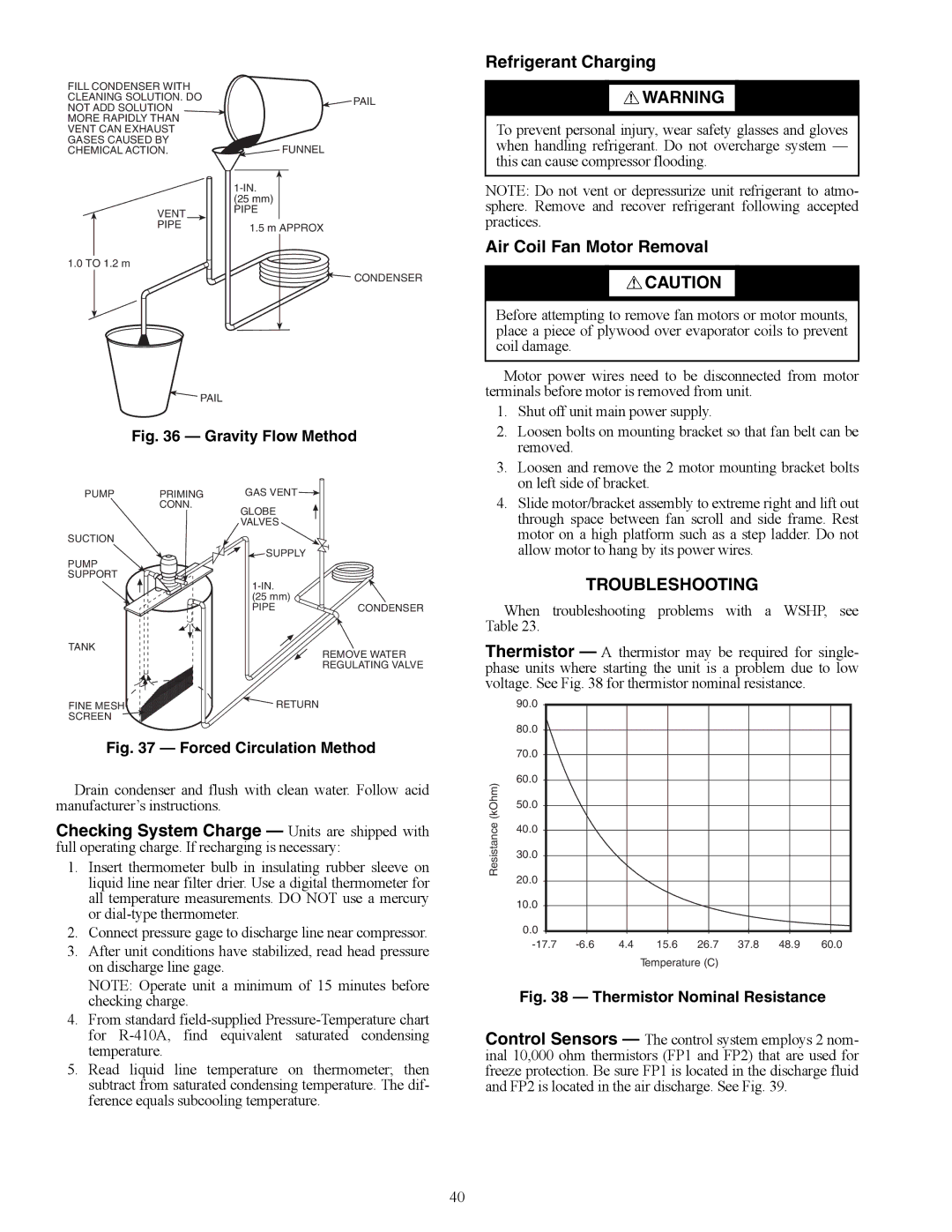
FILL CONDENSER WITH CLEANING SOLUTION. DO NOT ADD SOLUTION MORE RAPIDLY THAN VENT CAN EXHAUST GASES CAUSED BY CHEMICAL ACTION.
VENT
PIPE
1.0 TO 1.2 m
![]() PAIL
PAIL
![]() FUNNEL
FUNNEL
(25 mm)
PIPE
1.5 m APPROX
![]()
![]() CONDENSER
CONDENSER
Refrigerant Charging
![]() WARNING
WARNING
To prevent personal injury, wear safety glasses and gloves when handling refrigerant. Do not overcharge system — this can cause compressor flooding.
NOTE: Do not vent or depressurize unit refrigerant to atmo- sphere. Remove and recover refrigerant following accepted practices.
Air Coil Fan Motor Removal
![]() CAUTION
CAUTION
Before attempting to remove fan motors or motor mounts, place a piece of plywood over evaporator coils to prevent coil damage.
![]() PAIL
PAIL
Fig. 36 — Gravity Flow Method a50-8586
Motor power wires need to be disconnected from motor terminals before motor is removed from unit.
1. | Shut off unit main power supply. |
2. | Loosen bolts on mounting bracket so that fan belt can be |
| removed. |
3. | Loosen and remove the 2 motor mounting bracket bolts |
| on left side of bracket. |
PUMP PRIMING CONN.
SUCTION
PUMP
SUPPORT
GAS VENT ![]()
GLOBE
VALVES
![]() SUPPLY
SUPPLY
(25 mm)
PIPE
CONDENSER
4. Slide motor/bracket assembly to extreme right and lift out |
through space between fan scroll and side frame. Rest |
motor on a high platform such as a step ladder. Do not |
allow motor to hang by its power wires. |
TROUBLESHOOTING
When troubleshooting problems with a WSHP, see Table 23.
TANK
FINE MESH SCREEN
REMOVE WATER
REGULATING VALVE
![]() RETURN
RETURN
Thermistor — A thermistor may be required for single- phase units where starting the unit is a problem due to low voltage. See Fig. 38 for thermistor nominal resistance.
90.0 |
80.0 |
Fig. 37 — Forced Circulation Method
Drain condenser and flush with clean water. Follow acid manufacturer’s instructions.
Checking System Charge — Units are shipped with full operating charge. If recharging is necessary:
1.Insert thermometer bulb in insulating rubber sleeve on liquid line near filter drier. Use a digital thermometer for all temperature measurements. DO NOT use a mercury or
2.Connect pressure gage to discharge line near compressor.
3.After unit conditions have stabilized, read head pressure on discharge line gage.
NOTE: Operate unit a minimum of 15 minutes before checking charge.
4.From standard
5.Read liquid line temperature on thermometer; then subtract from saturated condensing temperature. The dif- ference equals subcooling temperature.
| 70.0 |
|
|
|
|
|
|
|
|
|
|
|
|
|
|
|
|
| |
(kOhm) | 60.0 |
|
|
|
|
|
|
|
|
|
|
|
|
|
|
|
| ||
50.0 |
|
|
|
|
|
|
|
| |
|
|
|
|
|
|
|
| ||
|
|
|
|
|
|
|
|
| |
istance | 40.0 |
|
|
|
|
|
|
|
|
|
|
|
|
|
|
|
| ||
30.0 |
|
|
|
|
|
|
|
| |
|
|
|
|
|
|
|
| ||
Res | 20.0 |
|
|
|
|
|
|
|
|
|
|
|
|
|
|
|
|
| |
|
|
|
|
|
|
|
|
| |
| 10.0 |
|
|
|
|
|
|
|
|
|
|
|
|
|
|
|
|
| |
| 0.0 |
|
|
|
|
|
|
|
|
|
|
|
|
|
|
|
|
| |
| 4.4 | 15.6 | 26.7 | 37.8 | 48.9 | 60.0 | |||
|
|
|
|
| Temperature (C) |
|
|
| |
Fig. 38 — Thermistor Nominal Resistance
Control Sensors — The control system employs 2 nom- inal 10,000 ohm thermistors (FP1 and FP2) that are used for freeze protection. Be sure FP1 is located in the discharge fluid and FP2 is located in the air discharge. See Fig. 39.
40