2.0INSTALLATION
2.1UNPACKING AND INSPECTION
Verify that there has been no damage to the shipping container. If damage exists then the container should be retained, as it will provide evidence of carrier caused problems. Such problems should be reported to the carrier immediately as well as to C&H. If there is no damage to the shipping container, carefully remove the instrument from its box and inspect for any signs of physical damage. If damage exists, report immediately to C&H.
2.2 HANDLING PRECAUTIONS
The components used in the EM405D are static sensitive. Damage may occur if proper static precautions are not taken. Installation of
CAUTION: Read the entire User's Manual before proceeding with the installation and application of power.
2.3 INSTALLATION OF M-MODULES
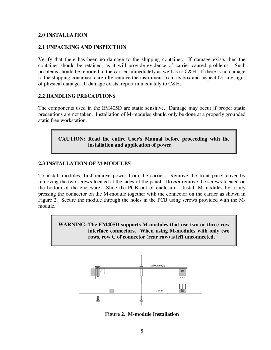
To install modules, first remove power from the carrier. Remove the front panel cover by removing the two screws located at the sides of the panel. Do not remove the screws located on the bottom of the enclosure. Slide the PCB out of enclosure. Install
WARNING: The EM405D supports
A B C |
Carrier
Figure 2. M-module Installation
5