Reg. 08 |
|
|
|
|
|
|
|
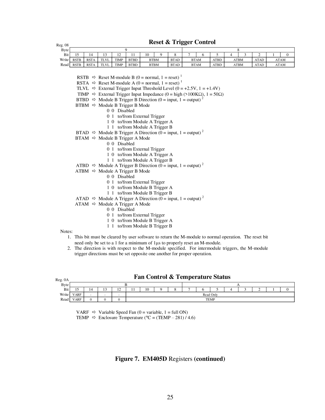
| Reset & Trigger Control |
|
|
|
|
|
|
| |||||||
|
|
|
|
|
|
|
|
|
|
|
|
|
|
|
|
|
|
|
|
|
|
| |
Byte |
|
|
|
|
|
| 9 |
|
|
|
|
|
|
|
|
| 8 |
|
|
|
| ||
Bit | 15 |
| 14 | 13 |
| 12 |
| 11 | 10 |
| 9 | 8 | 7 |
| 6 | 5 | 4 |
| 3 | 2 | 1 |
| 0 |
Write | RSTB | RSTA | TLVL |
| TIMP |
| BTBD | BTBM |
| BTAD |
| BTAM | ATBD |
| ATBM | ATAD |
| ATAM | |||||
Read | RSTB | RSTA | TLVL |
| TIMP |
| BTBD | BTBM |
| BTAD |
| BTAM | ATBD |
| ATBM | ATAD |
| ATAM | |||||
| RSTB | | Reset |
|
|
|
|
|
|
|
|
|
|
| |||||||||
| RSTA | Reset |
|
|
|
|
|
|
|
|
|
|
| ||||||||||
| TLVL | | External Trigger Input Threshold Level (0 = +2.5V, 1 = +1.4V) |
|
|
|
|
|
|
| |||||||||||||
| TIMP | | External Trigger Input Impedance (0 = high (>100KΩ), 1 = 50Ω) |
|
|
|
|
|
|
| |||||||||||||
| BTBD | | Module B Trigger B Direction (0 = input, 1 = output) 2 |
|
|
|
|
|
|
|
| ||||||||||||
| BTBM | Module B Trigger B Mode |
|
|
|
|
|
|
|
|
|
|
|
|
| ||||||||
|
|
|
| 0 | 0 | Disabled |
|
|
|
|
|
|
|
|
|
|
|
|
|
|
| ||
|
|
|
| 0 | 1 | to/from External Trigger |
|
|
|
|
|
|
|
|
|
|
|
| |||||
10 to/from Module A Trigger A
11 to/from Module A Trigger B
BTAD Module B Trigger A Direction (0 = input, 1 = output) 2 BTAM Module B Trigger A Mode
0 0 Disabled
0 1 to/from External Trigger
| 1 0 | to/from Module A Trigger A |
| 1 1 | to/from Module A Trigger B |
ATBD | Module A Trigger B Direction (0 = input, 1 = output) 2 | |
ATBM | Module A Trigger B Mode | |
| 0 0 | Disabled |
| 0 1 | to/from External Trigger |
| 1 0 | to/from Module B Trigger A |
| 1 1 | to/from Module B Trigger B |
ATAD | Module A Trigger A Direction (0 = input, 1 = output) 2 | |
ATAM | Module A Trigger A Mode | |
| 0 0 | Disabled |
| 0 1 | to/from External Trigger |
| 1 0 | to/from Module B Trigger A |
| 1 1 | to/from Module B Trigger B |
Notes:
1.This bit must be cleared by user software to return the
2.The direction is with respect to the
Reg. 0A |
|
|
|
|
|
|
| Fan Control & Temperature Status |
|
|
|
|
| |||||||||
|
|
|
|
|
|
|
|
|
|
|
|
|
|
|
|
|
|
|
|
|
| |
Byte |
|
|
|
|
|
| B |
|
|
|
|
|
|
|
|
| A |
|
|
| ||
Bit | 15 |
| 14 | 13 | 12 |
| 11 | 10 | 9 | 8 |
| 7 | 6 |
| 5 | 4 |
| 3 | 2 | 1 | 0 | |
Write | VARF |
| - |
| - | - |
|
|
|
|
|
|
| Read Only |
|
|
|
|
|
| ||
Read | VARF |
| 0 |
| 0 | 0 |
|
|
|
|
|
|
|
| TEMP |
|
|
|
|
|
| |
| VARF | Variable Speed Fan (0 = variable, 1 = full ON) |
|
|
|
|
|
|
|
|
|
| ||||||||||
| TEMP |
| Enclosure Temperature (°C = (TEMP – 281) / 4.6) |
|
|
|
|
|
|
|
|
| ||||||||||
Figure 7. EM405D Registers (continued)
25