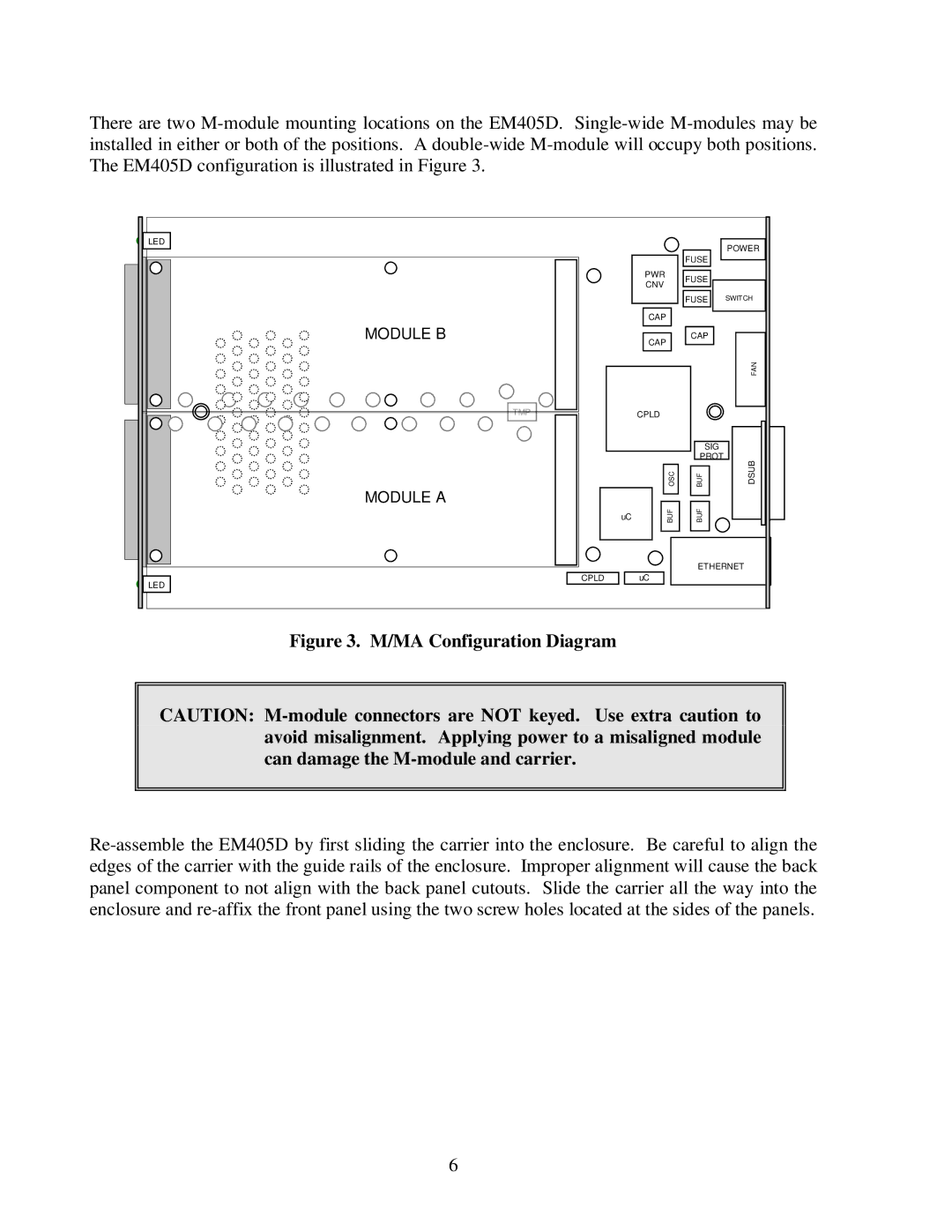
There are two M-module mounting locations on the EM405D. Single-wide M-modules may be installed in either or both of the positions. A double-wide M-module will occupy both positions. The EM405D configuration is illustrated in Figure 3.
 LED
LED
 LED
LED
| | POWER |
| | FUSE |
| PWR | FUSE |
| CNV |
| |
| | FUSE SWITCH |
CAP
Figure 3. M/MA Configuration Diagram
CAUTION: M-module connectors are NOT keyed. Use extra caution to avoid misalignment. Applying power to a misaligned module can damage the M-module and carrier.
Re-assemble the EM405D by first sliding the carrier into the enclosure. Be careful to align the edges of the carrier with the guide rails of the enclosure. Improper alignment will cause the back panel component to not align with the back panel cutouts. Slide the carrier all the way into the enclosure and re-affix the front panel using the two screw holes located at the sides of the panels.