Chapter 17 DLPs E100 to E199

DLP- E109 Drill Holes to Anchor and Provide Access to the Bay Assembly

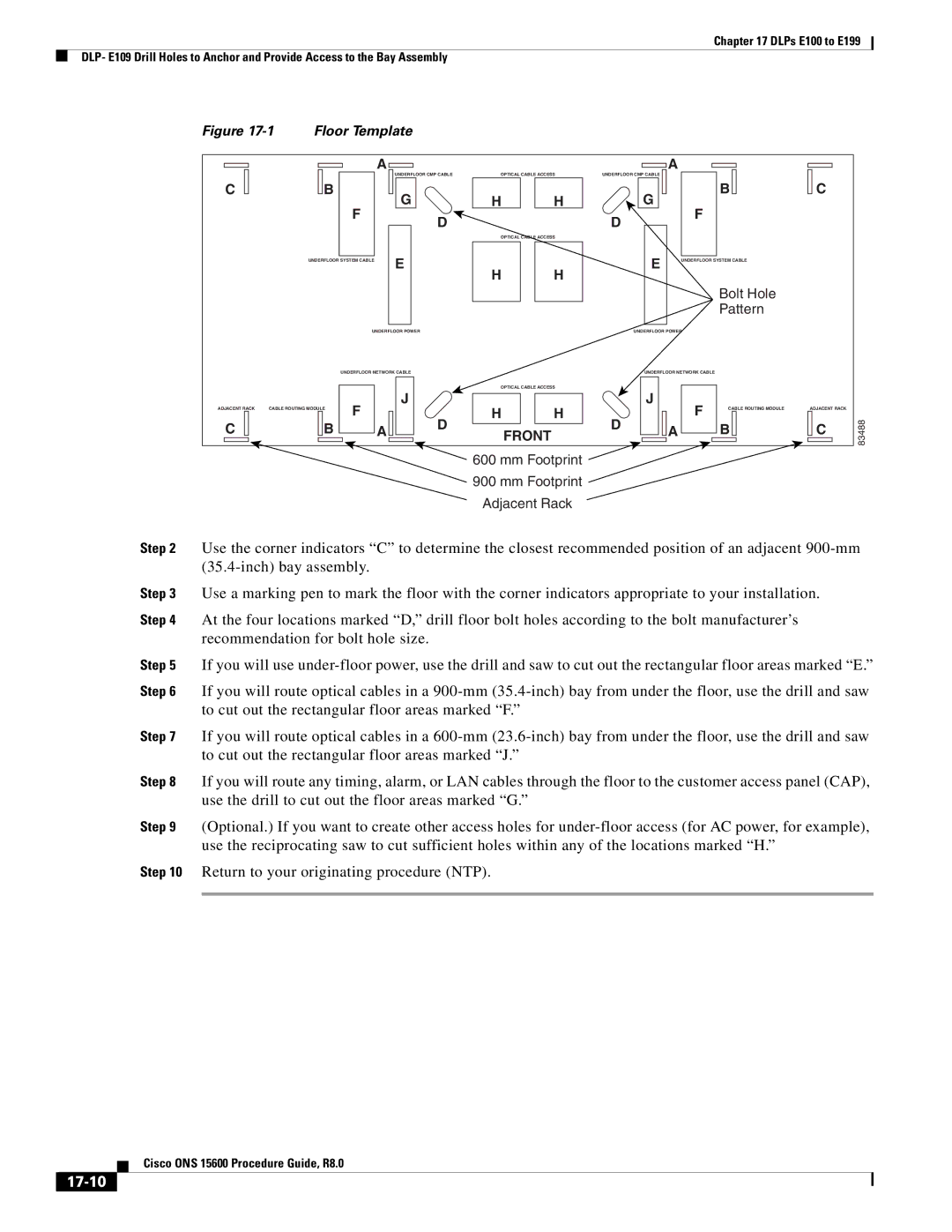
Figure 17-1 Floor Template


A


A


C


B


UNDERFLOOR CMP CABLE

OPTICAL CABLE ACCESS

UNDERFLOOR CMP CABLE


B


C


F


G


H


H


G


F


D

OPTICAL CABLE ACCESS

D


E


E


UNDERFLOOR SYSTEM CABLE


UNDERFLOOR SYSTEM CABLE


H


H


Bolt Hole


Pattern


UNDERFLOOR POWER


UNDERFLOOR POWER


UNDERFLOOR NETWORK CABLE


UNDERFLOOR NETWORK CABLE


OPTICAL CABLE ACCESS


J


J


ADJACENT RACK

CABLE ROUTING MODULE


F


H


H


F

CABLE ROUTING MODULE


ADJACENT RACK


C


B


A


D


D


A


B


C

83488


FRONT


600 mm Footprint

900 mm Footprint

Adjacent Rack

Step 2 Use the corner indicators “C” to determine the closest recommended position of an adjacent 900-mm (35.4-inch) bay assembly.

Step 3 Use a marking pen to mark the floor with the corner indicators appropriate to your installation.

Step 4 At the four locations marked “D,” drill floor bolt holes according to the bolt manufacturer’s recommendation for bolt hole size.

Step 5 If you will use under-floor power, use the drill and saw to cut out the rectangular floor areas marked “E.”

Step 6 If you will route optical cables in a 900-mm (35.4-inch) bay from under the floor, use the drill and saw to cut out the rectangular floor areas marked “F.”

Step 7 If you will route optical cables in a 600-mm (23.6-inch) bay from under the floor, use the drill and saw to cut out the rectangular floor areas marked “J.”

Step 8 If you will route any timing, alarm, or LAN cables through the floor to the customer access panel (CAP), use the drill to cut out the floor areas marked “G.”

Step 9 (Optional.) If you want to create other access holes for under-floor access (for AC power, for example), use the reciprocating saw to cut sufficient holes within any of the locations marked “H.”

Step 10 Return to your originating procedure (NTP).

Cisco ONS 15600 Procedure Guide, R8.0

17-10

Page 10
Image 10
Cisco Systems 15600 manual 17-10, Bolt Hole Pattern

15600 specifications

Cisco Systems 15600 is a powerful network router designed to meet the growing demands of enterprise and service provider networks. Equipped with advanced features and cutting-edge technology, the 15600 caters to a range of applications, from data centers to branch offices, supporting the evolving landscape of cloud computing and Internet of Things (IoT).

One of the standout features of the Cisco 15600 is its scalability. The router is built to handle increasing bandwidth requirements, making it ideal for environments where traffic is expected to grow. It supports a range of interface modules, allowing organizations to tailor their network connectivity according to their specific needs. This modular design not only ensures flexibility but also future-proofs the investment, as additional capacity can be added as network demands increase.

Cisco’s 15600 also incorporates advanced security features, such as built-in firewalls and support for secure VPN connections. This is crucial for businesses that prioritize data protection and need to safeguard their information against cyber threats. The router also supports multiple encryption protocols, allowing organizations to implement robust security measures without sacrificing performance.

With regard to performance, the 15600 offers high throughput rates, which are essential for handling large volumes of traffic efficiently. This enhanced performance is further supported by Cisco's innovative technologies, such as Application-Specific Integrated Circuits (ASICs) that optimize data processing. Additionally, the router utilizes Cisco’s Intelligent WAN (iWAN) capabilities, which enhance the overall performance and efficiency of WAN connections.

Another key characteristic of the 15600 is its support for software-defined networking (SDN). This enables organizations to automate network management, reduce operational costs, and improve agility in deploying applications. Using Cisco's software solutions, network administrators can manage the router through a centralized interface, simplifying operations and enhancing visibility into network performance.

Furthermore, the Cisco 15600 is designed with energy efficiency in mind. Its architecture minimizes power consumption while maintaining high performance levels, contributing to sustainability goals and reducing operational costs over time.

Overall, the Cisco Systems 15600 router stands out as a robust networking solution, offering unmatched scalability, security, performance, and operational efficiency. As organizations increasingly turn to cloud-based solutions and IoT devices, the capabilities of the 15600 position it as a critical component in modern network infrastructures.