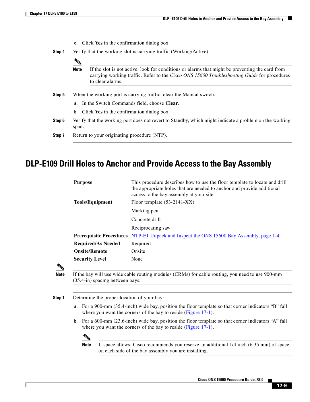
15600 specifications
Cisco Systems 15600 is a powerful network router designed to meet the growing demands of enterprise and service provider networks. Equipped with advanced features and cutting-edge technology, the 15600 caters to a range of applications, from data centers to branch offices, supporting the evolving landscape of cloud computing and Internet of Things (IoT).One of the standout features of the Cisco 15600 is its scalability. The router is built to handle increasing bandwidth requirements, making it ideal for environments where traffic is expected to grow. It supports a range of interface modules, allowing organizations to tailor their network connectivity according to their specific needs. This modular design not only ensures flexibility but also future-proofs the investment, as additional capacity can be added as network demands increase.
Cisco’s 15600 also incorporates advanced security features, such as built-in firewalls and support for secure VPN connections. This is crucial for businesses that prioritize data protection and need to safeguard their information against cyber threats. The router also supports multiple encryption protocols, allowing organizations to implement robust security measures without sacrificing performance.
With regard to performance, the 15600 offers high throughput rates, which are essential for handling large volumes of traffic efficiently. This enhanced performance is further supported by Cisco's innovative technologies, such as Application-Specific Integrated Circuits (ASICs) that optimize data processing. Additionally, the router utilizes Cisco’s Intelligent WAN (iWAN) capabilities, which enhance the overall performance and efficiency of WAN connections.
Another key characteristic of the 15600 is its support for software-defined networking (SDN). This enables organizations to automate network management, reduce operational costs, and improve agility in deploying applications. Using Cisco's software solutions, network administrators can manage the router through a centralized interface, simplifying operations and enhancing visibility into network performance.
Furthermore, the Cisco 15600 is designed with energy efficiency in mind. Its architecture minimizes power consumption while maintaining high performance levels, contributing to sustainability goals and reducing operational costs over time.
Overall, the Cisco Systems 15600 router stands out as a robust networking solution, offering unmatched scalability, security, performance, and operational efficiency. As organizations increasingly turn to cloud-based solutions and IoT devices, the capabilities of the 15600 position it as a critical component in modern network infrastructures.

