Chapter 4 Router Installation
Typical Installation
Installing the Cisco Secure Router 520
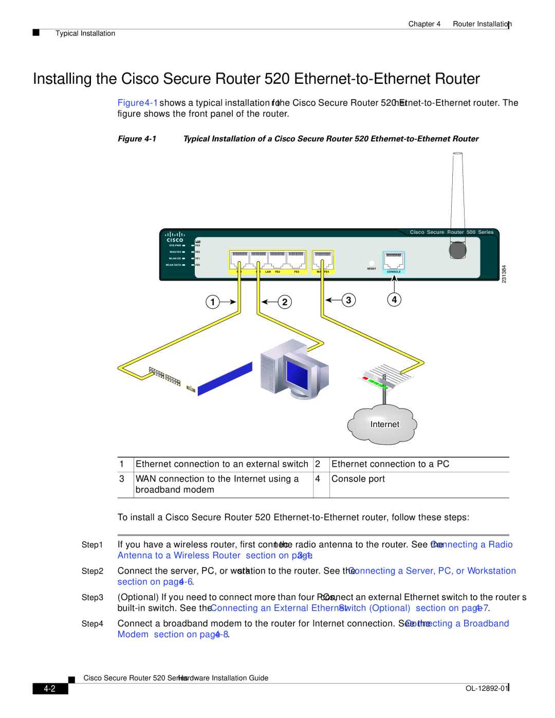
Figure 4-1 shows a typical installation for the Cisco Secure Router 520 Ethernet-to-Ethernet router. The figure shows the front panel of the router.
Figure 4-1 Typical Installation of a Cisco Secure Router 520 Ethernet-to-Ethernet Router
Cisco Secure Router 500 Series
231384
1 | 2 | 3 | 4 |
|
|
| Internet |
|
|
|
|
1 | Ethernet connection to an external switch | 2 | Ethernet connection to a PC |
|
|
|
|
3 | WAN connection to the Internet using a | 4 | Console port |
| broadband modem |
|
|
|
|
|
|
To install a Cisco Secure Router 520
Step 1 If you have a wireless router, first connect the radio antenna to the router. See the “Connecting a Radio Antenna to a Wireless Router” section on page
Step 2 Connect the server, PC, or workstation to the router. See the “Connecting a Server, PC, or Workstation” section on page
Step 3 (Optional) If you need to connect more than four PCs, connect an external Ethernet switch to the router’s
Step 4 Connect a broadband modem to the router for Internet connection. See the “Connecting a Broadband Modem” section on page
Cisco Secure Router 520 Series Hardware Installation Guide
|
| |
|