Chapter 4 Router Installation
Typical Installation
Step 5 Connect the AC adapter to the router. See the “Connecting the AC Adapter” section on page
Step 6 To configure the router software by using the
Step 7 (Optional) To use the console port as a backup link to the WAN port in case the ADSL service goes down, connect an analog modem to the console port. See the “Connecting an Asynchronous Modem to the Console Port” section on page
Installing the Cisco Secure Router 520 ADSL-over-POTS Router
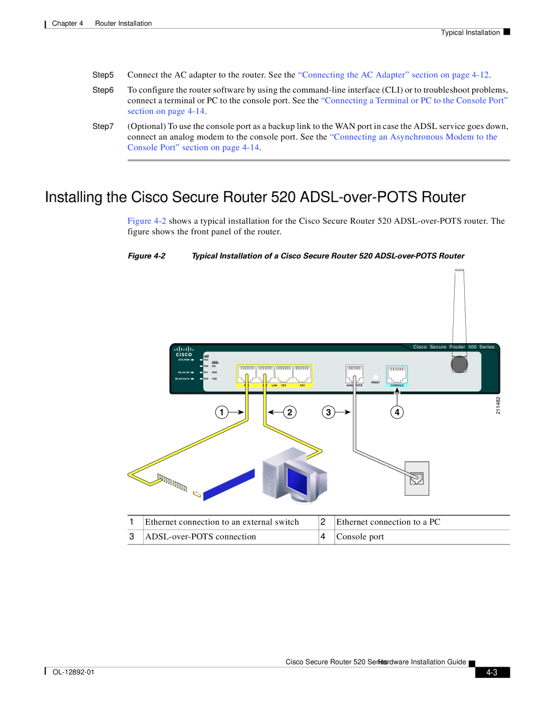
Figure 4-2 shows a typical installation for the Cisco Secure Router 520 ADSL-over-POTS router. The figure shows the front panel of the router.
Figure 4-2 Typical Installation of a Cisco Secure Router 520 ADSL-over-POTS Router
Cisco Secure Router 500 Series
1 | 2 | 3 | 4 |
211482
1 | Ethernet connection to an external switch | 2 | Ethernet connection to a PC |
|
|
|
|
3 | 4 | Console port | |
|
|
|
|
Cisco Secure Router 520 Series Hardware Installation Guide
|
| ||
|
|