Chapter 4 Router Installation
Verifying Router Operation
To connect the console port on the router to an asynchronous modem, follow these steps:
Step 1 Connect the
Step 2 Connect the
Step 3 Connect one end of the
Step 4 (Optional) Connect one end of an
Verifying Router Operation
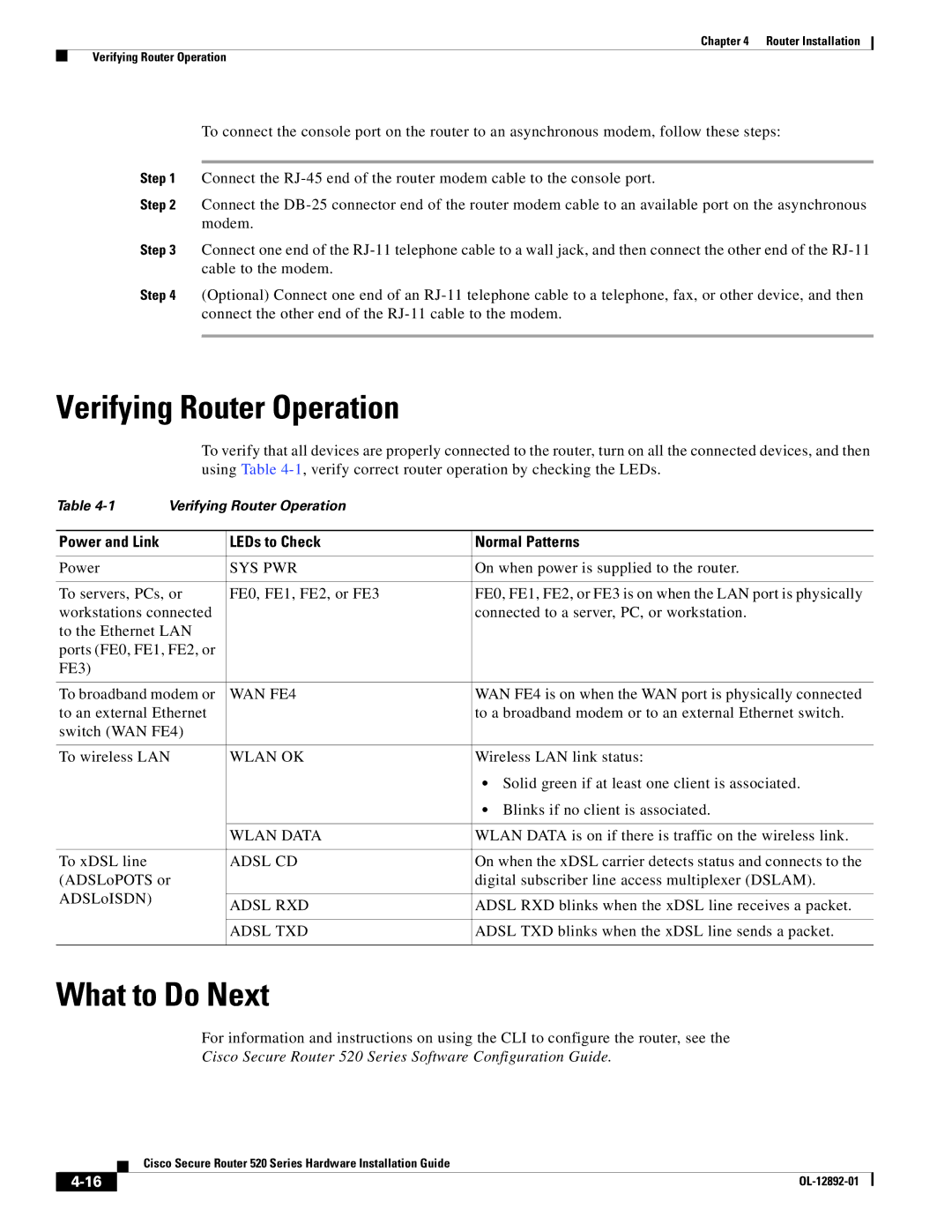
To verify that all devices are properly connected to the router, turn on all the connected devices, and then using Table
Table | Verifying Router Operation |
| |
|
|
|
|
Power and Link |
| LEDs to Check | Normal Patterns |
|
|
|
|
Power |
| SYS PWR | On when power is supplied to the router. |
|
|
| |
To servers, PCs, or | FE0, FE1, FE2, or FE3 | FE0, FE1, FE2, or FE3 is on when the LAN port is physically | |
workstations connected |
| connected to a server, PC, or workstation. | |
to the Ethernet LAN |
|
| |
ports (FE0, FE1, FE2, or |
|
| |
FE3) |
|
|
|
|
|
| |
To broadband modem or | WAN FE4 | WAN FE4 is on when the WAN port is physically connected | |
to an external Ethernet |
| to a broadband modem or to an external Ethernet switch. | |
switch (WAN FE4) |
|
| |
|
|
| |
To wireless LAN | WLAN OK | Wireless LAN link status: | |
|
|
| • Solid green if at least one client is associated. |
|
|
| • Blinks if no client is associated. |
|
|
|
|
|
| WLAN DATA | WLAN DATA is on if there is traffic on the wireless link. |
|
|
|
|
To xDSL line |
| ADSL CD | On when the xDSL carrier detects status and connects to the |
(ADSLoPOTS or |
| digital subscriber line access multiplexer (DSLAM). | |
ADSLoISDN) |
|
|
|
| ADSL RXD | ADSL RXD blinks when the xDSL line receives a packet. | |
|
| ||
|
|
|
|
|
| ADSL TXD | ADSL TXD blinks when the xDSL line sends a packet. |
|
|
|
|
What to Do Next
For information and instructions on using the CLI to configure the router, see the
Cisco Secure Router 520 Series Software Configuration Guide.
| Cisco Secure Router 520 Series Hardware Installation Guide |
