Chapter 1 Product Overview
Cable Side
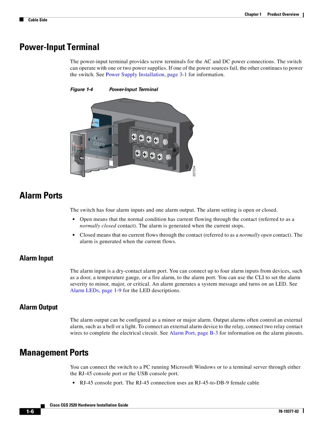
Power-Input Terminal
The
Figure 1-4 Power-Input Terminal
Cisco CGS 2520
207234
Alarm Ports
The switch has four alarm inputs and one alarm output. The alarm setting is open or closed.
•Open means that the normal condition has current flowing through the contact (referred to as a normally closed contact). The alarm is generated when the current stops.
•Closed means that no current flows through the contact (referred to as a normally open contact). The alarm is generated when the current flows.
Alarm Input
The alarm input is a
Alarm Output
The alarm output can be configured as a minor or major alarm. Output alarms often control an external alarm, such as a bell or a light. To connect an external alarm device to the relay, connect two relay contact wires to complete the electrical circuit. See Alarm Port, page
Management Ports
You can connect the switch to a PC running Microsoft Windows or to a terminal server through either the
•
Cisco CGS 2520 Hardware Installation Guide
| ||
|