Chapter 3 Power Supply Installation
Power Supply Module Installation
Step 5 Use a ratcheting torque screwdriver to tighten the ground screws to 30
Step 6 Attach the other end of the ground wire to a grounded bare metal surface, such as a ground bus or a grounded bare rack.
Installing the Power Supply Module in the Switch
Step 1 We recommend that power be off at the AC or DC circuits. Locate the circuit breakers, turn them OFF, and tape them in the OFF position.
Note If the power is not off at the AC or DC circuit breaker, do not touch the
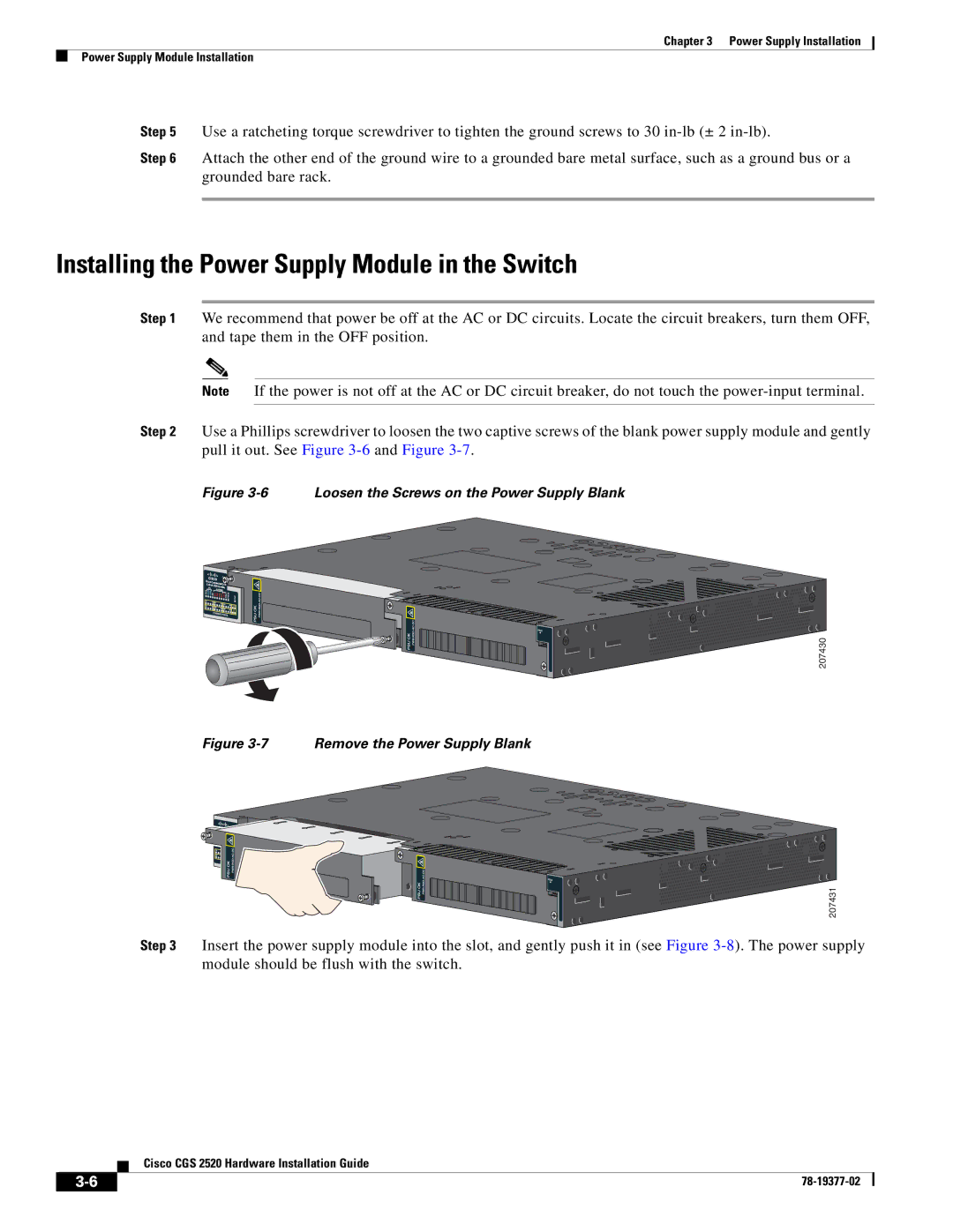
Step 2 Use a Phillips screwdriver to loosen the two captive screws of the blank power supply module and gently pull it out. See Figure
Figure 3-6 Loosen the Screws on the Power Supply Blank
Cisco |
|
|
Connected | Grid | |
Switch |
| |
| 2500 Series | |
207430
Figure 3-7 Remove the Power Supply Blank
207431
Step 3 Insert the power supply module into the slot, and gently push it in (see Figure
Cisco CGS 2520 Hardware Installation Guide
| ||
|