Chapter 3 Power Supply Installation
Power Supply Module Installation
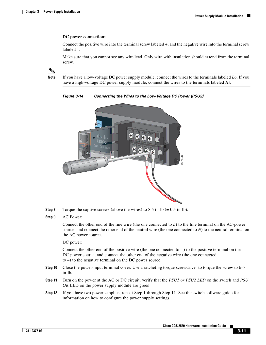
DC power connection:
Connect the positive wire into the terminal screw labeled +, and the negative wire into the terminal screw labeled
Make sure that you cannot see any wire lead. Only wire with insulation should extend from the terminal screw.
Note If you have a
Figure 3-14 Connecting the Wires to the Low-Voltage DC Power (PSU2)
Cisco CGS 25200
![]() 207428
207428
Step 8 Torque the captive screws (above the wires) to 8.5
Step 9 AC Power:
Connect the other end of the line wire (the one connected to L) to the line terminal on the
DC power:
Connect the other end of the positive wire (the one connected to +) to the positive terminal on the
to
Step 10 Close the
Step 11 Turn on the power at the AC or DC circuit, verify that the PSU1 or PSU2 LED on the switch and PSU OK LED on the power supply module are green.
Step 12 If you have two power supplies, repeat Step 1 through Step 11. See the switch software guide for information on how to configure the power supply settings.
Cisco CGS 2520 Hardware Installation Guide
|
| ||
|
|