Chapter 3 Power Supply Installation
Power Supply Module Installation
Follow these steps to install a
Step 1 Use a Phillips screwdriver or a ratcheting torque screwdriver with a Phillips head to remove the ground screw from the cable side of the switch. You need the screw in Step 4.
Step 2 Strip the
Figure 3-3 Stripping the Ground Wire
0.25 in. (6.3 mm) ± 0.02 in. (0.5 mm) ![]()
![]()
60531
Step 3 Insert the ground wire into the terminal lug, and crimp the terminal to the wire (see Figure
Figure 3-4 Crimping the Terminal Lug
280938
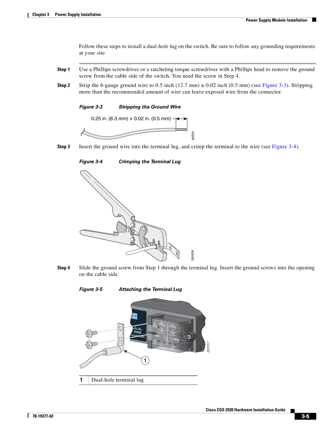
Step 4 Slide the ground screw from Step 1 through the terminal lug. Insert the ground screws into the opening on the cable side.
Figure 3-5 Attaching the Terminal Lug
![]() V~,
V~,
Cisco
1
![]() 207217
207217
1
Dual-hole terminal lug
Cisco CGS 2520 Hardware Installation Guide
|
| ||
|
|