Appendix B Connector and Cable Specifications
Connector Specifications
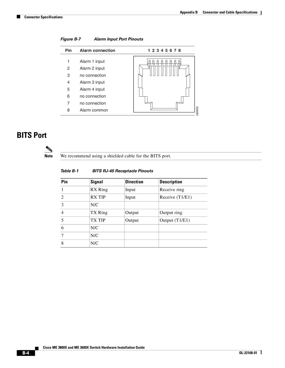
Figure B-7 Alarm Input Port Pinouts
Pin | Alarm connection |
1Alarm 1 input
2Alarm 2 input
3no connection
4Alarm 3 input
5Alarm 4 input
6no connection
7no connection
8Alarm common
1 2 3 4 5 6 7 8
2 09508
BITS Port
Note We recommend using a shielded cable for the BITS port.
Table | BITS |
| |
|
|
|
|
Pin | Signal | Direction | Description |
|
|
|
|
1 | RX Ring | Input | Receive ring |
|
|
|
|
2 | RX TIP | Input | Receive (T1/E1) |
|
|
|
|
3 | N/C |
|
|
|
|
|
|
4 | TX Ring | Output | Output ring |
|
|
|
|
5 | TX TIP | Output | Output (T1/E1) |
|
|
|
|
6 | N/C |
|
|
|
|
|
|
7 | N/C |
|
|
|
|
|
|
8 | N/C |
|
|
|
|
|
|
Cisco ME 3800X and ME 3600X Switch Hardware Installation Guide
|
|
| |
|
|
