Chapter 1 Product Overview
Front Panel
Switch LED Panels
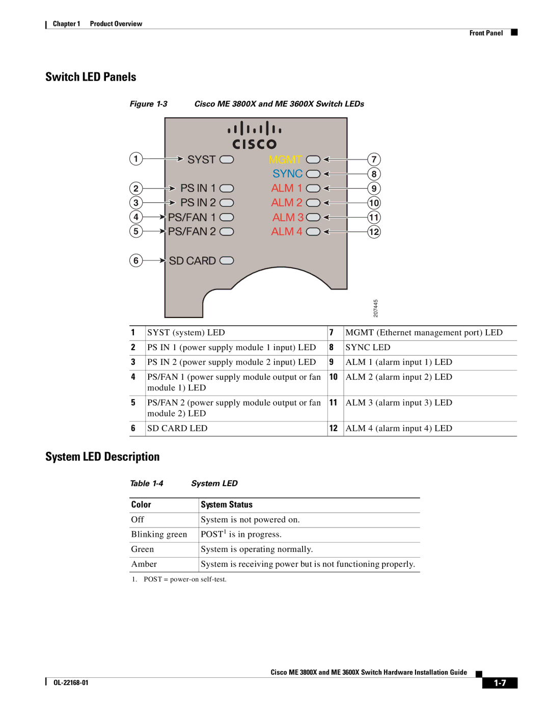
Figure 1-3 Cisco ME 3800X and ME 3600X Switch LEDs
1 | SYST | MGMT | 7 |
|
| SYNC | 8 |
2 | PS IN 1 | ALM 1 | 9 |
3 | PS IN 2 | ALM 2 | 10 |
4 | PS/FAN 1 | ALM 3 | 11 |
5 | PS/FAN 2 | ALM 4 | 12 |
6 SD CARD
|
|
| 207445 |
|
|
|
|
1 | SYST (system) LED | 7 | MGMT (Ethernet management port) LED |
|
|
|
|
2 | PS IN 1 (power supply module 1 input) LED | 8 | SYNC LED |
|
|
|
|
3 | PS IN 2 (power supply module 2 input) LED | 9 | ALM 1 (alarm input 1) LED |
|
|
|
|
4 | PS/FAN 1 (power supply module output or fan | 10 | ALM 2 (alarm input 2) LED |
| module 1) LED |
|
|
|
|
|
|
5 | PS/FAN 2 (power supply module output or fan | 11 | ALM 3 (alarm input 3) LED |
| module 2) LED |
|
|
|
|
|
|
6 | SD CARD LED | 12 | ALM 4 (alarm input 4) LED |
|
|
|
|
System LED Description
Table | System LED | |
|
|
|
Color |
| System Status |
|
|
|
Off |
| System is not powered on. |
|
|
|
Blinking green |
| POST1 is in progress. |
Green |
| System is operating normally. |
|
|
|
Amber |
| System is receiving power but is not functioning properly. |
|
|
|
1. POST =
Cisco ME 3800X and ME 3600X Switch Hardware Installation Guide
|
| ||
|
|