Chapter 1 Product Overview
Front Panel
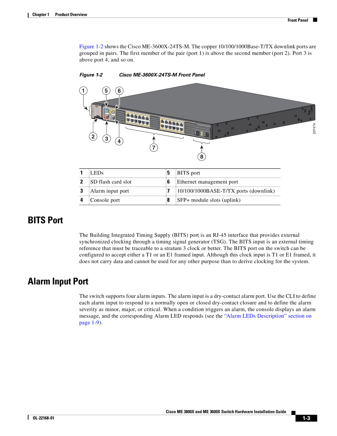
Figure 1-2 shows the Cisco ME-3600X-24TS-M. The copper 10/100/1000Base-T/TX downlink ports are grouped in pairs. The first member of the pair (port 1) is above the second member (port 2). Port 3 is above port 4, and so on.
Figure 1-2 Cisco ME-3600X-24TS-M Front Panel
1 | 5 | 6 |
| SYST | M GM T | BITS |
|
|
|
|
|
|
|
|
|
|
|
|
|
|
|
| PS IN 1 | SYNC |
| M G M T |
|
|
|
|
|
|
|
|
|
|
|
|
|
|
| PS IN 2 | ALM 1 |
|
|
|
|
|
|
|
|
|
|
|
|
|
|
|
|
| PS/FAN 1 | ALM 2 |
| 1X | 1 | 2 |
|
|
|
|
|
|
|
|
|
|
|
|
| PS/FAN 2 | ALM 3 |
|
|
| 3 | 4 |
|
|
|
|
|
|
|
|
|
|
|
|
| ALM 4 |
|
|
|
| 5 | 6 | 8 |
|
|
|
|
|
|
|
|
|
| SD CARD |
|
|
|
|
|
| 7 | 10 |
|
|
|
|
|
|
|
| |
|
|
|
|
|
|
|
| 9 | 12 |
|
|
|
|
|
|
| ||
|
|
|
|
|
|
|
|
|
| 11 |
|
|
|
|
|
|
| |
|
|
|
|
|
|
|
|
|
|
| 11X |
|
|
|
|
|
|
|
|
|
|
|
|
|
|
|
|
|
| 13X | 13 | 14 | 16 |
|
|
|
|
|
|
| ALARM S |
|
|
|
|
|
|
|
|
| 15 |
|
|
|
| |
|
|
| CO NSO LE |
|
|
|
|
|
|
|
|
| 17 | 18 | 19 | 20 |
| |
|
|
|
|
|
|
|
|
|
|
|
|
|
|
|
| 21 22 | 24 | |
|
|
|
|
|
|
|
|
|
|
|
|
|
|
|
|
| 23 | |
|
|
|
|
|
|
|
|
|
|
|
|
|
|
|
|
|
| 23X |
|
|
|
| 2X |
|
|
|
|
|
|
|
|
|
|
|
|
|
|
|
|
|
|
|
|
|
|
|
|
| 12X |
|
|
|
|
|
|
|
|
|
|
|
|
|
|
|
|
|
| 14X |
|
|
|
|
|
|
|
|
|
|
|
|
|
|
|
|
|
|
|
|
|
|
|
|
| 1 |
| 2 |
|
|
|
|
|
|
|
|
|
|
|
|
|
|
|
| 24X |
|
|
|
|
|
|
|
|
|
|
|
|
|
|
|
|
| 2 | |
|
| 3 | 4 |
|
|
|
|
|
|
|
|
|
|
|
|
|
| |
|
|
|
|
|
|
|
|
|
|
|
|
|
|
|
|
| ||
|
|
|
|
|
|
|
|
|
| 7 |
|
|
|
|
|
|
| |
|
|
|
|
|
|
|
|
|
|
|
|
|
|
|
|
|
| |
|
|
|
|
|
|
|
|
|
|
|
|
|
|
|
|
|
| 8 |
1 | LEDs |
|
|
|
|
|
|
|
|
|
|
| 5 |
|
| BITS port | ||
2 SD flash card slot |
|
|
|
|
|
|
| 6 |
|
| Ethernet management port | |||||||
3 | Alarm input port |
|
|
|
|
|
|
|
| 7 |
|
| ||||||
4 | Console port |
|
|
|
|
|
|
|
|
| 8 SFP+ module slots (uplink) | |||||||
BITS Port
207474
The Building Integrated Timing Supply (BITS) port is an
Alarm Input Port
The switch supports four alarm inputs. The alarm input is a
Cisco ME 3800X and ME 3600X Switch Hardware Installation Guide
|
| ||
|
|