Chapter 9 Removal and Replacement Procedures

Removing and Replacing the Fan Assembly

Removing the Fan Assembly

The fan assembly is designed to be removed and replaced while the system is operating without presenting an electrical hazard or damage to the system.

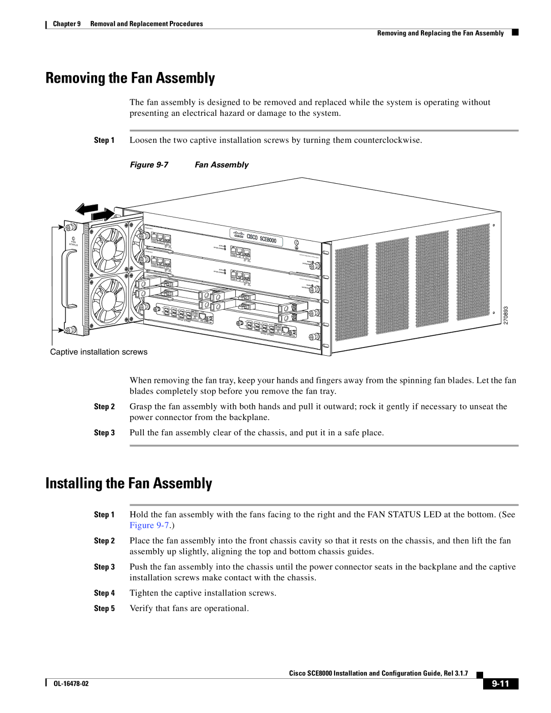
Step 1 Loosen the two captive installation screws by turning them counterclockwise.

Figure 9-7

Fan Assembly

SCE8000-SCM-E

FAN STATUS

OPTICAL


BYPASS

CONSOLE


PORT 1


1000

LINK


STATUS


10

100


OPTICAL BYPASS


ACTIVE


SCE8000-SCM-E


OPTICAL


BYPASS

AUX


PORT 2


10

100

LINK


1000

ACTIVE


OPTICAL


BYPASS

CONSOLE


PORT 1


10 100

LINK


STATUS


1000

A


OPTICAL BYPASS


CTIVE


SCE8000-SI


OPTICAL


BYPASS

AUX


ACTIVE/LI


PORT 2


10 100

LINK


1000

ACTIVE


ACTIVE/LI


ACTIVE/L


/LINK


ACTIVE


TX


TX


RX


TX

TX


A

C

CTRL


RX


B

D


RX

RX


A

B


C

D


OPTICAL

BYPA


STATUS

OPB-


SS1


SCE8K-


TX


MM


TX


RX

TX

TX


RX


RX

RX


OPTICAL

BYPASS2


A

C

CTRL

B

D

A

B


C

D


STATUS


OPB-SCE8K-MM

SCE8000

EXTENDED SERVICE


CONTROL MODULE


MASTER

SYSTEM POWER

SCE8000

EXTENDED SERVICE


CONTROL MODULE


MASTER

SYSTEM POWER

270893

Captive installation screws

When removing the fan tray, keep your hands and fingers away from the spinning fan blades. Let the fan blades completely stop before you remove the fan tray.

Step 2 Grasp the fan assembly with both hands and pull it outward; rock it gently if necessary to unseat the power connector from the backplane.

Step 3 Pull the fan assembly clear of the chassis, and put it in a safe place.

Installing the Fan Assembly

Step 1 Hold the fan assembly with the fans facing to the right and the FAN STATUS LED at the bottom. (See Figure 9-7.)

Step 2 Place the fan assembly into the front chassis cavity so that it rests on the chassis, and then lift the fan assembly up slightly, aligning the top and bottom chassis guides.

Step 3 Push the fan assembly into the chassis until the power connector seats in the backplane and the captive installation screws make contact with the chassis.

Step 4 Tighten the captive installation screws.

Step 5 Verify that fans are operational.


Cisco SCE8000 Installation and Configuration Guide, Rel 3.1.7


OL-16478-02


9-11


Page 133
Image 133
Cisco Systems SCE8000 manual Removing the Fan Assembly, Installing the Fan Assembly

SCE8000 specifications

Cisco Systems SCE8000 is an advanced service control edge solution designed to enhance the management and performance of service provider networks. Targeted at carriers and large enterprises, the SCE8000 is characterized by its capacity to efficiently handle traffic management, quality of service (QoS), and policy enforcement across various services including voice, video, and data.

One of the main features of the SCE8000 is its scalability. The platform supports a high-density architecture, allowing service providers to seamlessly expand their networks to accommodate growing traffic demands. This scalability is complemented by an impressive throughput, which enables the handling of millions of concurrent sessions, making it ideal for environments with significant user activity.

The SCE8000 employs advanced traffic management capabilities, leveraging deep packet inspection (DPI) technology. This allows for granular visibility into network traffic, enabling service providers to make informed decisions about resource allocation and policy application. Additionally, the device supports multiple protocol analysis, ensuring compatibility across various network services and enhancing overall efficiency.

Quality of Service (QoS) is another critical characteristic of the SCE8000. The platform provides sophisticated mechanisms to prioritize traffic, thereby ensuring that delay-sensitive applications such as VoIP and video streaming receive the necessary bandwidth. This capability is enhanced by Cisco's intelligent traffic shaping and congestion management features, which work together to optimize the user experience even in congested network conditions.

The SCE8000 also integrates robust security features, including session initiation protocol (SIP) security, to protect against malicious attacks and maintain service integrity. This is particularly important in today's cyber landscape where service providers must safeguard their infrastructure from various threats.

Automation and programmability are essential characteristics of the SCE8000, enabling operators to implement policies quickly and efficiently. This feature allows for dynamic scaling and rapid deployment of new services, significantly reducing the time to market for new offerings.

In conclusion, Cisco Systems SCE8000 stands out as a powerful platform for managing service provider networks. With its high scalability, advanced traffic management, quality of service assurance, robust security features, and automation capabilities, the SCE8000 enables service providers to deliver a superior customer experience while optimizing their operational efficiency. This makes it an invaluable asset for any organization looking to enhance its network performance and service delivery.