| Appendices ~ Appendix B: Pinouts |
|
|
| 21 | ||
|
|
| |||||
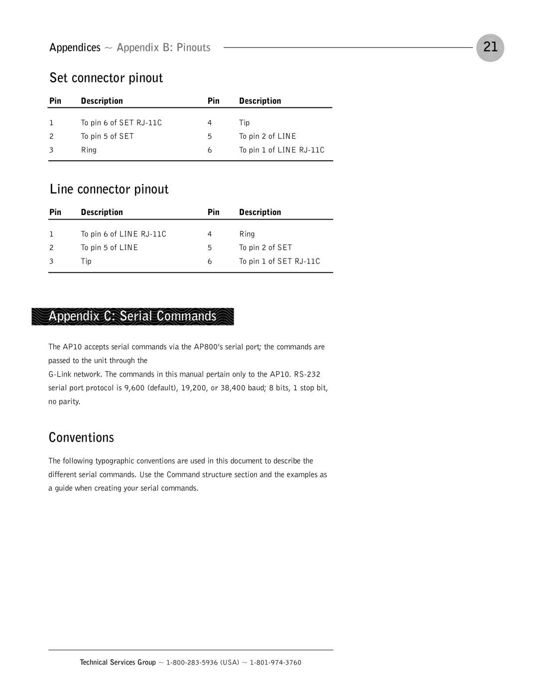
| Set connector pinout |
|
|
|
|
| |
|
|
|
|
|
| ||
| Pin | Description | Pin | Description | |||
|
|
|
|
|
|
| |
1 | To pin 6 of SET | 4 | Tip | ||||
2 | To pin 5 of SET | 5 | To pin 2 of LINE | ||||
3 | Ring | 6 | To pin 1 of LINE | ||||
|
|
|
|
|
|
| |
| Line connector pinout |
|
|
|
|
| |
| Pin | Description | Pin | Description | |||
|
|
|
|
| |||
1 | To pin 6 of LINE | 4 | Ring | ||||
2 | To pin 5 of LINE | 5 | To pin 2 of SET | ||||
3 | Tip | 6 | To pin 1 of SET | ||||
|
|
|
|
|
|
|
|
Appendix C: Serial Commands
The AP10 accepts serial commands via the AP800’s serial port; the commands are passed to the unit through the
Conventions
The following typographic conventions are used in this document to describe the different serial commands. Use the Command structure section and the examples as a guide when creating your serial commands.