Maintenance and Service Guide
Page
Contents
Illustrated Parts Catalog
Screw Listing Index
Product Description
Models and Features
Models
Key
Key Description Options
T4X
Taiwan
Features
Serial
Power Management
External Computer Components
Front and Left Side Panel Components
Component Function
Front and Left Side Panel Components
Right Side and Rear Panel Components
Right Side and Rear Panel Components
Right Side and Rear Panel Components
Keyboard components are shown in -4 and described in Table
Fn key
Keyboard Components
Top Components
Top Components
Top Components
Bottom Components
Bottom Components
Bottom Components
Design Overview
Troubleshooting
Using the PhoenixBIOS Setup Utility
Troubleshooting Flowcharts
Troubleshooting Flowcharts Overview
Section Description
Initial Troubleshooting
No Power, Part
From Section No Power, Part
Power outlet
From Section No Power, Part Open Computer
No Video, Part
From Section No Video, Part Remove
Non Functioning Docking Station if applicable
Reseat power Cord in docking Station Power outlet
No Operating System OS Loading
No OS Loading from Hard Drive, Part
From Section
System Files on hard Drive? Install OS Reboot
No OS Loading from Diskette Drive
No OS Loading from CD- or DVD-ROM Drive
Undock
No Audio, Part
From Section No Audio, Part
Non Functioning Device
Non Functioning Keyboard
Non Functioning Pointing Device
Network or Modem Connection
Serial Number Location
Illustrated Parts Catalog
Computer System Major Components
Computer System Major Components
Computer System Major Components
Computer System Major Components
Heat sink
PC Card assembly
Disk cell RTC battery
Description Number Speakers
Computer System Major Components
Base enclosure
Battery packs
Item Description Number Mini PCI Communications Boards
Media Bay devices
Miscellaneous Plastics Kit Components
Miscellaneous Plastics Kit Components Spare Part Number
Item Description
Miscellaneous Hardware Kit Components Spare Part Number
Miscellaneous Hardware Kit Components
Cable Kit Components Spare Part Number
Cable Kit Components
Optical drives
Mass Storage Devices
Mass Storage Devices
Description Number Diskette drive 239035-001 Hard drives
Miscellaneous Spare Parts not illustrated
Miscellaneous
Logo kit
Power cord, black, 6 feet
Description Number External AC adapter
50W slim AC adapter
Tools Required
Service Considerations
Cables and Connectors
Preventing Damage to Removable Drives
Plastic Parts
Maintenance and Service Guide
Preventing Electrostatic Damage
Packaging and Transporting Precautions
Workstation Precautions
Grounding Equipment and Methods
Material Use Voltage Protection Level
Typical Electrostatic Voltage Levels
Static-Shielding Materials
Relative Humidity Event 10% 40% 55%
Removal and Replacement Procedures
Serial Number
Section Description Removed
Disassembly Sequence Chart
Disassembly Sequence Chart
# of Screws
Computer Feet
Preparing the Computer for Disassembly
Removing the Hinge Covers
Hinge Covers
Keyboard Cover Spare Part Number Information
Keyboard
Remove the two pewter M2.5 × 7.0 screws that secure
Display Spare Part Number Information
Display
Reverse the above procedure to install the display
Removing the EMI Shield
EMI Shield
Top Cover Spare Part Number Information
Top Cover
Removing the Top Cover Screws
Disconnecting Top Cover Connectors
10. Removing the Top Cover
TouchPad Spare Part Number Information
TouchPad
11. Removing the TouchPad Screws
Remove the TouchPad bracket and TouchPad from the top cover
Speakers Spare Part Number Information
Speakers
13. Routing the Speaker Cables
14. Removing the Speakers
Microphone
Reverse the above procedure to install the microphone
16. Removing the Display Lid Switch Board
Display Lid Switch Board
Heat Sink
Heat Sink
Reverse the above procedure to install the heat sink
Infrared Board Spare Part Number Information
Infrared Board
Board to the base enclosure
System Board Spare Part Number Information
System Board
19. Removing the System Board Screwlocks
20. Removing the System Board Screws
21.Lifting the System Board
Reverse the above procedure to install the system board
PC Card Assembly Spare Part Number Information
PC Card Assembly
Reverse the above procedure to install the PC Card assembly
Mini PCI Board Spare Part Number Information
Mini PCI Board
Reverse the above procedure to install the mini PCI board
Disk Cell RTC Battery Spare Part Number Information
Disk Cell RTC Battery
25. Removing the Disk Cell RTC Battery
Temperature
Dimensions
Standalone Battery Power Requirements
AC Adapter Power Requirements
Relative Humidity non condensing
Shock
Vibration
Inch XGA, TFT Display
Interface type
Logical configuration
Hard Drives
15 GB 10 GB User capacity per drive1
Transfer rate
15 GB 10 GB Physical configuration
Buffer size3
Disk rotational speed
Diskette Drive
CD-ROM Drive
DVD-ROM Drive
Disk thickness Track pitch
Audio output level
AC Adapter
Weight Power supply input
Battery Packs
Energy
Environmental requirements
Hardware DMA System Function
System DMA
Hardware IRQ System Function
System Interrupts
System I/O Addresses
16F Unused
VGA
Size Memory Address System Function
System Memory Map
Table A-2 Microphone
Pin Signal Audio out Ground
Pin Signal Audio Ground
Table A-1 Stereo Speaker/Headphone
Pin Signal
Table A-3 External Keyboard/Mouse
Table A-4 RJ-11 Modem
Table A-6 Universal Serial Bus
Table A-5 RJ-45 Network Interface
Table A-7 Serial
Table A-8 External Monitor
Table A-9 Parallel
General Requirements
Conductor Power Cord Set
Conductor Power Cord Set Requirements-By Country
Country-Specific Requirements
Country Accredited Agency Applicable Note Number
Maintenance and Service Guide
Screw Listing
Table C-1 M2.5 × 7.0 Screw
Head
Color Qty Length Thread Width Pewter M2.5
Table C-1 M2.5 × 7.0 Screw
Table C-1 M2.5 × 7.0 Screw
Head Color Qty Length Thread Width
Color Qty Length Thread Width Silver M2.5
Table C-2 M2.5 × 8.0 Screw
Color Qty Length Thread Width Silver
Table C-3 M2 × 5.5 Screw
Table C-4 M2.5 × 4.5 Screw
Color Qty Length Thread Width Black M2.5 Where used
Table C-4 M2.5 × 4.5 Screw
Table C-4 M2.5 × 4.5 Screw
Table C-4 M2.5 × 4.5 Screw
Table C-5 M2 ×
Table C-6 M2.5 × 4.0 Screw
Head
Table C-7 M2.5 × 3.0 Screw
Table C-8 M2 × 6.0 Screw
Table C-9 M1 × 4.0 Screw
Color Qty Length Thread Width Silver Where used
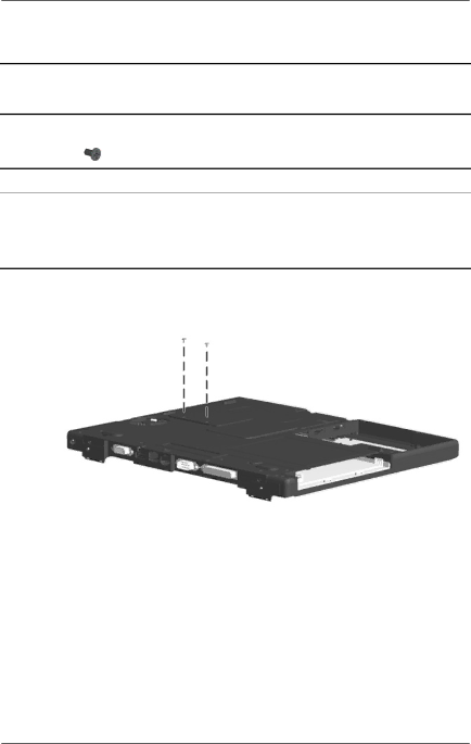
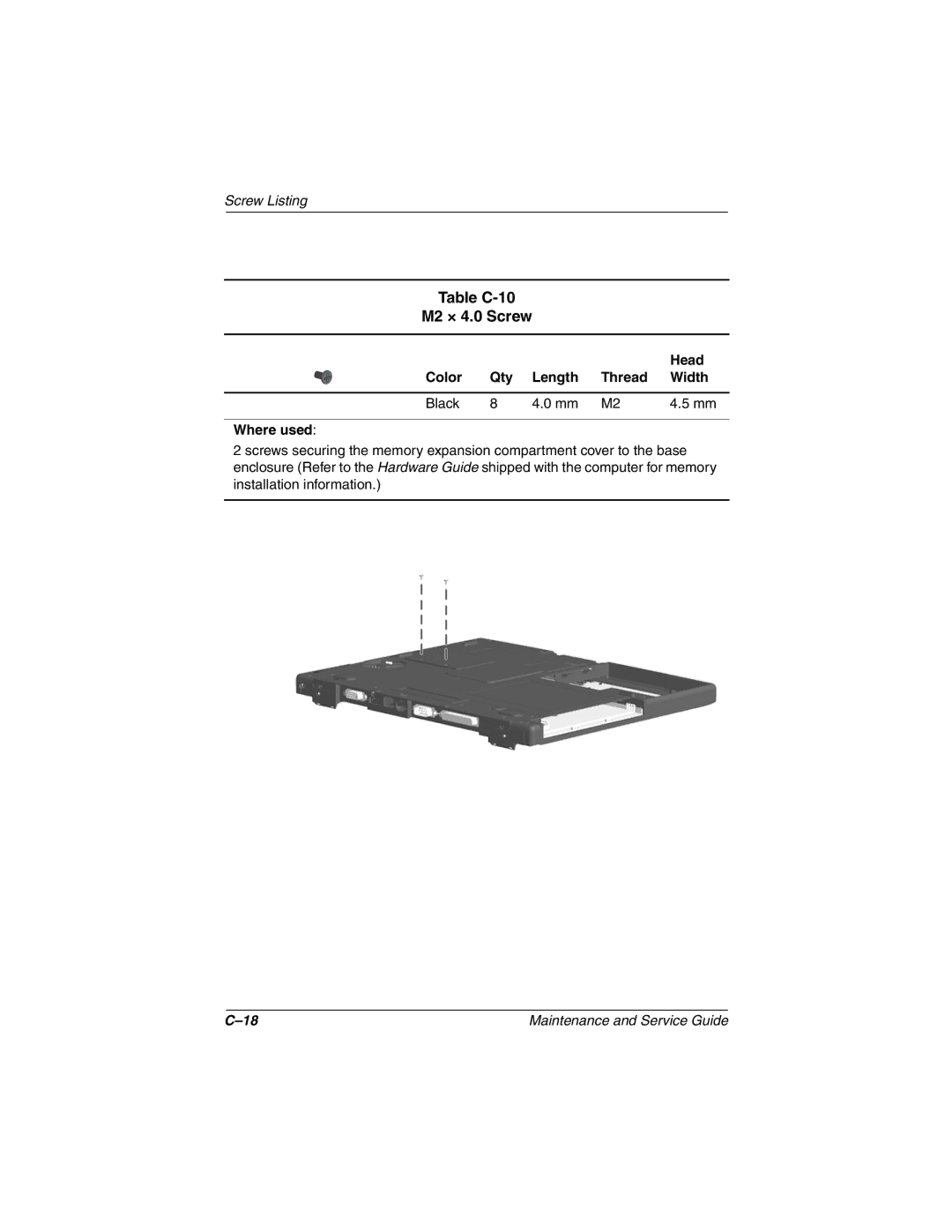
Table C-10 M2 × 4.0 Screw
Table C-10 M2 × 4.0 Screw
Table C-11 M2 × 14.5 Screw
Table C-12 M2 × 5.0 Screw
Head Color Qty Length Socket Width
Table C-13 Mm Screwlock
Index
Index-2
Index-3
Spare part number
Index-5
Troubleshooting