Maintenance and Service Guide
Page
Contents
Illustrated Parts Catalog
Removal and Replacement Preliminaries
Removal and Replacement Procedures
Screw Listing Index
Maintenance and Service Guide
Product Description
Product Description
Models
Compaq Tablet PC TC1000 Naming Conventions
Key
Key Description Options
Compaq Tablet PC TC1000 Models
470045-153
470046-345 CTC1000
470046-342 CTC1000
Features
Maintenance and Service Guide
Clearing a Password
Power Management
Component Function
Tablet PC External Components
Front Panel Components
Front Panel Components
Top Side Components
Top Side Components
Top Side Components
Left Side Components
Left Side Components
Left Side Components
Right Side Components
Right Side Components
Ctrl+alt+delete command
Bottom Side Components
Bottom Side Components
Bottom Components
Bottom Components
Bottom Components
Bottom Components
Keyboard Components
Keyboard Front Panel Components
Keyboard Front Panel Components
10. Keyboard Front Panel Components
Keyboard Front Panel Components
11. Keyboard Rear Panel and Bottom Components
Keyboard Rear Panel and Bottom Components
Docking Station Components
12. Docking Station Front and Left Side Components
Docking Station Front and Left Side Components
13. Docking Station Rear Panel and Right Side Components
Docking Station Rear Panel and Right Side Components
Design Overview
Troubleshooting
Computer Setup and Diagnostics Utilities
Using Computer Setup
File Menu
Select To Do This
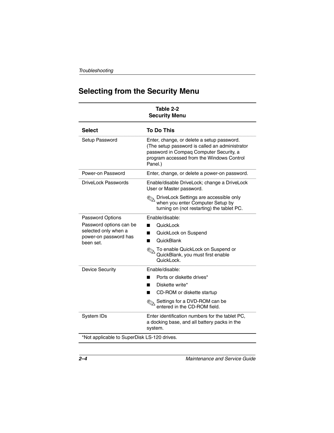
Selecting from the Security Menu
Security Menu
Selecting from the Advanced Menu
Advanced Menu
Advanced Menu
Using Compaq Diagnostics
Obtaining, Saving, or Printing Configuration Information
Obtaining, Saving, or Printing Diagnostic Test Information
Maintenance and Service Guide
Flowchart Description
Troubleshooting Flowcharts
Troubleshooting Flowcharts Overview
Flowchart 2.1-Initial Troubleshooting
Is there power? Go to Section No Power
Flowchart 2.2-No Power, Part
Power? Go to Section No Power Part Power up On AC Reset
Flowchart 2.3-No Power, Part
Flowchart 2.4-No Power, Part
Internal
Flowchart 2.5-No Power, Part
From Section No Power, Part Open Tablet PC
Flowchart 2.6-No Video, Part
Flowchart 2.7-No Video, Part
No Video, Part
Flowchart 2.8-Nonfunctioning Docking Station if applicable
Flowchart 2.9-No Operating System OS Loading
Flowchart 2.10-No OS Loading from Hard Drive, Part
Flowchart 2.11-No OS Loading from Hard Drive, Part
Flowchart 2.12-No OS Loading from Hard Drive, Part
Flowchart 2.13-No OS Loading from Diskette Drive
Flowchart 2.14-No OS Loading from CD- or DVD-ROM Drive
Flowchart 2.15-No Audio, Part
Undock
Flowchart 2.16-No Audio, Part
Flowchart 2.17-Nonfunctioning Device
Nonfunctioning Device Reseat
Flowchart 2.18-Nonfunctioning Keyboard
OK?
Flowchart 2.19-Nonfunctioning Pointing Device
Flowchart 2.20-No Network or Modem Connection
Illustrated Parts Catalog
Serial Number Location
Tablet PC System Major Components
Tablet PC Major Components
Spare Parts Tablet PC System Major Components
Item Description Number Display components
Miscellaneous Cable Kit, includes
Miscellaneous Plastic/Hardware Kit, includes
Tablet PC Major Components
Switch board
Wireless local area network LAN board
Battery pack, Li ion
Real time clock RTC battery
Item Description
Miscellaneous Cable Kit Components
Miscellaneous Cable Kit Components Spare Part Number
Miscellaneous Plastic/Hardware Kit Contents
Miscellaneous Plastics/Hardware Kit Components
Description Number Tablet PC TC1000 Keyboards
Keyboard
Tablet PC TC1000 Keyboard
Docking Station
Optional Docking Station
Compaq Tablet PC TC1000 Docking Station Components
Docking Station Components
Miscellaneous
Spare Parts Miscellaneous not illustrated
Removal and Replacement Preliminaries
Tools Required
Service Considerations
Plastic Parts
Preventing Damage to Removable Drives
Packaging and Transporting Precautions
Preventing Electrostatic Damage
Workstation Precautions
Grounding Equipment and Methods
Typical Electrostatic Voltage Levels
Static-Shielding Materials
Relative Humidity Event 10% 40% 55%
Material Use Voltage Protection Level
Removal and Replacement Preliminaries
Removal and Replacement Procedures
Serial Number
Section Description Removed
Disassembly Sequence Chart
Disassembly Sequence Chart
Preparing the Tablet PC for Disassembly
Battery Pack Spare Part Number Information
Reverse the preceding procedures to install the battery pack
Removal and Replacement Procedures
Removing the Mini PCI Communications Board
Mini PCI Communications Board Spare Part Number Information
Removing the Memory Expansion Board
Memory Expansion Board Spare Part Number Information
Removing the Hard Drive Cover
Reverse the preceding procedures to install the hard drive
Hard Drive Spare Part Number Information
Real Time Clock RTC Battery
RTC Battery Spare Part Number Information
Display Panel Assembly
Removing the Display Panel Assembly Screws
Removal and Replacement Procedures
11. Removing the Display Panel Assembly
12. Removing the Display Panel Bracket
13. Disconnecting the Display Panel Cables
14. Removing the Display Panel
15. Removing the Digitizer
16. Removing the Bridge Battery
Speaker Assembly
Speaker Assembly Spare Part Number Information
18. Removing the Speaker Cable
Digitizer Cable
19. Removing the Digitizer Cable
System Board
System Board Spare Part Number Information
20. Removing the Keyboard Release Assembly
21. Installing the Keyboard Release Assembly
22. Removing the PC Card and CompactFlash Card Slot Devices
23. Removing the Switch Board Cable
24. Removing the System Board Screws
Reverse the preceding procedures to install the system board
Fan and Heat Sink
Fan and Heat Sink Spare Part Number Information
26. Removing the EMI Shield
27. Removing the Fan and Heat Sink
Modem Cable
28. Removing the Modem Cable
Switch Board
Switch Board Spare Part Number Information
Reverse the preceding procedures to install the switch board
Docking Station Components Spare Part Number Information
30. Removing the Top Case Screws
31. Removing the Top Case
32. Disconnecting the Docking Stand Cable
33. Removing the Docking Stand and Pivot Arm
34. Removing the Board Assembly Screws
35. Removing the Board Assembly
Tablet PC
Shock
Vibration
Inch XGA, TFT Display
Hard Drives
60 GB 30 GB Physical configuration
Buffer size3
Disk rotational speed
Transfer rate
Diskette size
Light
Height
Bytes per sector
Track pitch Access time
Applicable disk
Center hole diameter Disk diameter
Disk thickness
Track pitch
Audio output level
Center hole diameter
Cell, Li Ion Battery Pack
External AC Adapter
System DMA
Hardware DMA System Function
System Interrupts
Hardware IRQ System Function
System I/O Addresses
16F Unused
VGA
System Memory Map
Size Memory Address System Function
Pin Signal
Table A-1 RJ-45 Network Interface
Table A-2 RJ-11 Modem
Table A-3 Universal Serial Bus
Table A-4 External Monitor
Pin Signal Audio out Ground
Pin Signal Audio Ground
Table A-5 Stereo Speaker/Headphone
Table A-6 Microphone
Power Cord Set Requirements
Conductor Power Cord Set
Country Accredited Agency Applicable Note Number
Conductor Power Cord Set Requirements
Country-Specific Requirements
Power Cord Set Requirements
Power Cord Set Requirements
Screw Listing
Head
Color Qty Length Thread Width Silver Where used
Table C-1 Phillips M2.0 × 4.0 Screw
Figure C-2. Phillips M2.0 × 4.0 Screw Locations
Table C-2 Torx M2.5 × 7.0 Screw
Figure C-3. Torx M2.5 × 7.0 Screw Locations
Figure C-4. Torx M2.5 × 7.0 Screw Locations
Figure C-5. Torx M2.5 × 7.0 Screw Locations
Table C-3 Phillips M2.0 × 5.0 Screw
Figure C-6. Phillips M2.0 × 5.0 Screw Locations
Figure C-7. Phillips M2.0 × 5.0 Screw Locations
Figure C-8. Phillips M2.0 × 5.0 Screw Locations
Table C-4 Phillips M2.0 × 3.5 Screw
Figure C-9. Phillips M2.0 × 3.5 Screw Locations
Figure C-10. Phillips M2.0 × 3.5 Screw Locations
Color Qty Length Thread Width Black Where used
Table C-5 Phillips M2.5 × 5.0 Screw
Color Qty Length Thread Width Silver 12.0 mm Where used
Table C-6 Phillips M2.5 × 12.0 Screw
Table C-7 Phillips M2.5 × 6.0 Screw
Figure C-13. Phillips M2.5 × 6.0 Screw Locations
Index
Index-2
Index-3
Index-4
Index-5
Index-6
Index-7
Index-8