CY7C1360C
CY7C1362C
TAP AC Switching Characteristics Over the Operating Range[10, 11]
Parameter | Description | Min. | Max. | Unit |
Clock |
|
|
|
|
tTCYC | TCK Clock Cycle Time | 50 |
| ns |
tTF | TCK Clock Frequency |
| 20 | MHz |
tTH | TCK Clock HIGH time | 20 |
| ns |
tTL | TCK Clock LOW time | 20 |
| ns |
Output Times |
|
|
| |
|
|
|
|
|
tTDOV | TCK Clock LOW to TDO Valid |
| 10 | ns |
tTDOX | TCK Clock LOW to TDO Invalid | 0 |
| ns |
|
|
|
| |
|
|
|
|
|
tTMSS | TMS | 5 |
| ns |
tTDIS | TDI | 5 |
| ns |
tCS | Capture | 5 |
| ns |
Hold Times |
|
|
|
|
tTMSH | TMS Hold after TCK Clock Rise | 5 |
| ns |
tTDIH | TDI Hold after Clock Rise | 5 |
| ns |
tCH | Capture Hold after Clock Rise | 5 |
| ns |
3.3V TAP AC Test Conditions
Input pulse levels | VSS to 3.3V |
Input rise and fall times | 1 ns |
Input timing reference levels | 1.5V |
Output reference levels | 1.5V |
Test load termination supply voltage | 1.5V |
2.5V TAP AC Test Conditions
Input pulse levels | VSS to 2.5V |
Input rise and fall time | 1 ns |
Input timing reference levels | 1.25V |
Output reference levels | 1.25V |
Test load termination supply voltage | 1.25V |
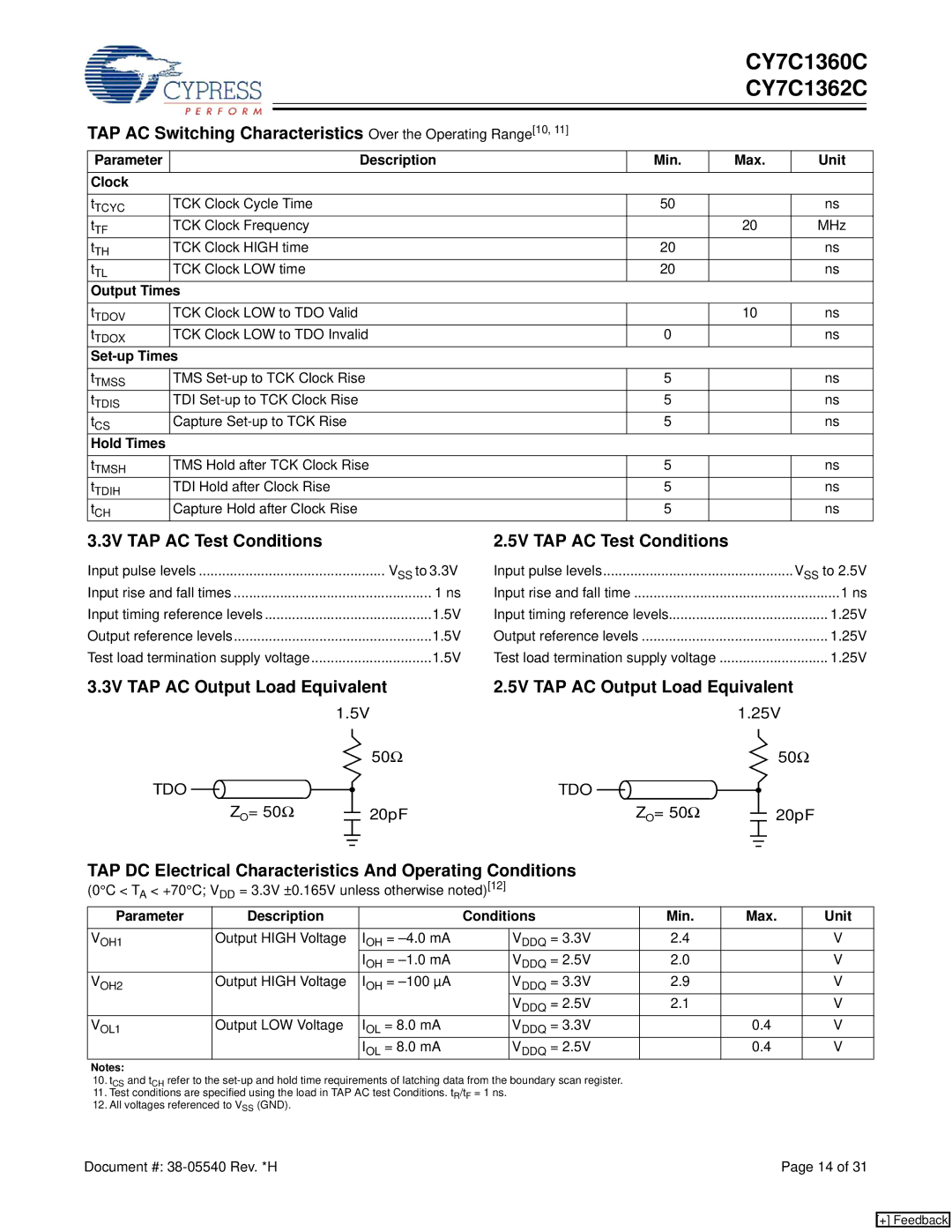
3.3V TAP AC Output Load Equivalent | 2.5V TAP AC Output Load Equivalent |
| ||||||||||||||||||||||||||||||
|
|
|
|
|
|
| 1.5V |
|
|
|
|
|
|
|
|
| 1.25V |
| ||||||||||||||
|
|
|
|
|
|
|
|
|
|
|
|
| 50Ω |
|
|
|
|
|
|
|
|
|
|
|
|
|
|
|
| 50Ω |
| |
TDO |
|
|
|
|
|
|
|
|
|
|
|
|
|
| TDO |
|
|
|
|
|
|
|
|
|
|
|
|
|
|
|
|
|
|
|
|
|
|
|
|
|
|
|
|
|
|
|
|
|
|
|
|
|
|
|
|
|
|
|
|
| |||||
|
|
|
|
|
|
|
|
|
|
|
|
|
|
|
|
|
|
|
|
|
|
|
|
|
|
|
|
|
| |||
|
|
|
| ZO= 50Ω |
|
|
| 20pF |
|
|
|
|
| ZO= 50Ω |
|
|
|
|
|
|
|
| 20pF |
| ||||||||
|
|
|
|
|
|
|
|
|
|
|
|
|
|
|
|
|
|
|
|
|
|
| ||||||||||
|
|
|
|
|
|
|
|
|
|
|
|
|
|
|
|
|
|
|
|
|
|
|
|
|
|
| ||||||
|
|
|
|
|
|
|
|
|
|
|
|
|
|
|
|
|
|
|
|
|
|
|
|
|
|
|
|
|
|
|
|
|
|
|
|
|
|
|
|
|
|
|
|
|
|
|
|
|
|
|
|
|
|
|
|
| |||||||||
TAP DC Electrical Characteristics And Operating Conditions |
|
|
|
|
|
|
|
|
|
|
|
|
|
|
| |||||||||||||||||
(0°C < T < +70°C; V | DD | = 3.3V ±0.165V unless otherwise noted)[12] |
|
|
|
|
|
|
|
|
|
|
|
|
|
|
| |||||||||||||||
A |
|
|
|
|
|
|
|
|
|
|
|
|
|
|
|
|
|
|
|
|
|
|
|
|
|
|
|
|
|
| ||
Parameter |
|
|
|
| Description |
|
|
| Conditions |
|
| Min. |
| Max. |
| Unit | ||||||||||||||||
|
|
|
|
|
|
|
|
|
|
|
|
|
|
|
|
|
|
|
|
|
| |||||||||||
VOH1 |
| Output HIGH Voltage |
|
| IOH = |
| VDDQ = 3.3V |
|
| 2.4 |
|
|
|
|
|
|
|
|
|
|
| V | ||||||||||
|
|
|
|
|
|
|
|
|
|
|
|
| IOH = |
| VDDQ = 2.5V |
|
| 2.0 |
|
|
|
|
|
|
|
|
|
|
| V | ||
VOH2 |
| Output HIGH Voltage |
|
| IOH = |
| VDDQ = 3.3V |
|
| 2.9 |
|
|
|
|
|
|
|
|
|
|
| V | ||||||||||
|
|
|
|
|
|
|
|
|
|
|
|
|
|
| VDDQ = 2.5V |
|
| 2.1 |
|
|
|
|
|
|
|
|
|
|
| V | ||
VOL1 |
| Output LOW Voltage |
|
| IOL = 8.0 mA |
| VDDQ = 3.3V |
|
|
|
|
| 0.4 |
| V | |||||||||||||||||
|
|
|
|
|
|
|
|
|
|
|
|
| IOL = 8.0 mA |
| VDDQ = 2.5V |
|
|
|
|
| 0.4 |
| V | |||||||||
Notes:
10.tCS and tCH refer to the
11.Test conditions are specified using the load in TAP AC test Conditions. tR/tF = 1 ns.
12.All voltages referenced to VSS (GND).
Document #: | Page 14 of 31 |
[+] Feedback