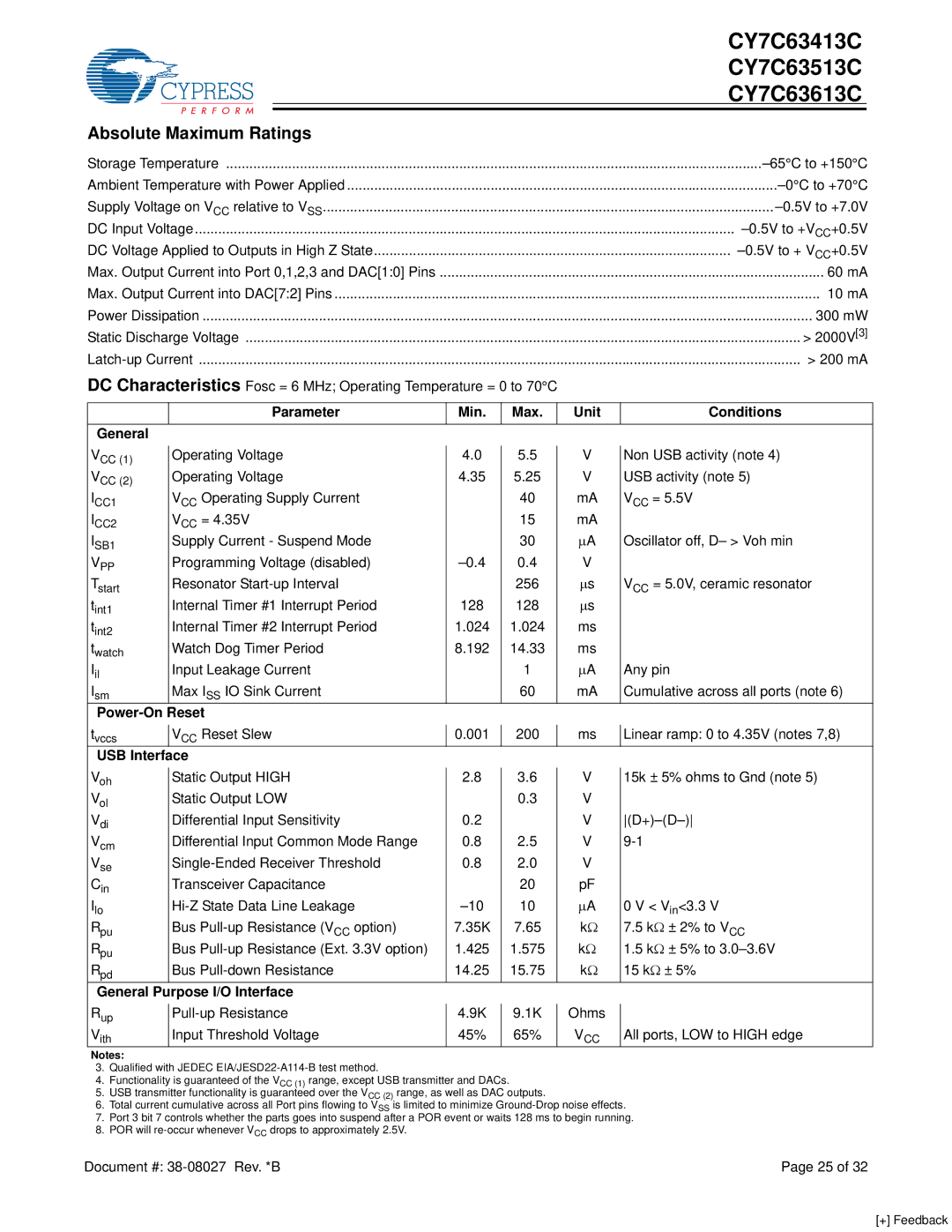
CY7C63613C, CY7C63413C, CY7C63513C specifications
The Cypress CY7C63513C, CY7C63413C, and CY7C63613C are versatile programmable logic devices that are part of the Cypress family of microcontrollers designed for diverse applications. These devices are particularly well-suited for embedded systems, consumer electronics, and industrial control systems due to their robust features and technologies.One of the standout characteristics of these devices is their programmable architecture, which allows for flexible design implementations. The CY7C63513C features 32 programmable I/O pins and an 8-bit microcontroller core, which provides ample resource allocation for various input/output operations. The device supports various communication interfaces, including SPI and I2C, enabling seamless integration into different system configurations.
The CY7C63413C is a highly adaptable component, offering similar features but with an enhanced flexibility in its I/O configuration, making it ideal for applications that require quick prototyping and development cycles. Its extensive instruction set allows for more complex processing tasks, catering to advanced applications in automation and signal processing.
On the other hand, the CY7C63613C provides an advanced level of integration with built-in support for multiple power management modes. This feature is crucial in modern battery-operated devices where energy conservation is a primary concern. Its low-power operation enhances the usability in portable applications while still maintaining performance.
In terms of performance, all three devices boast high-speed operation, with clock frequencies reaching up to 24 MHz. This ensures that they can efficiently handle tasks that require real-time processing, such as sensor data management and control algorithms. The devices are also equipped with an on-chip EEPROM and RAM, allowing for data storage and quick retrieval.
In addition to their performance characteristics, the CY7C63513C, CY7C63413C, and CY7C63613C are designed with reliability in mind. They incorporate robust error detection and correction features, ensuring data integrity during operation. This reliability is essential for critical applications, such as automotive systems and industrial automation.
Overall, the Cypress CY7 series presents an appealing solution for developers looking for a blend of flexibility, performance, and reliability in their embedded designs. Their programmability and support for multiple communication protocols make them a formidable choice in today’s fast-paced technological landscape, paving the way for innovative applications across various industries.

