CY7C63413C

CY7C63513C

CY7C63613C

Table 11.Possible Port Configurations

Port Configuration bits

Pin Interrupt Bit

Driver Mode

Interrupt Polarity

11

X

Resistive

-


10

0

CMOS Output

disabled


10

1

Open Drain

disabled


01

X

Open Drain

-


00

X

Open Drain

+ (default)


In “Resistive” mode, a 7-kpull-up resistor is conditionally enabled for all pins of a GPIO port. The resistor is enabled for any pin that has been written as a “1.” The resistor is disabled on any pin that has been written as a “0.” An I/O pin will be driven high through a 7-kpull-up resistor when a “1” has been written to the pin. Or the output pin will be driven LOW, with the pull-up disabled, when a “0” has been written to the pin. An I/O pin that has been written as a “1” can be used as an input pin with an integrated 7-kpull-up resistor. Resistive mode selects a negative (falling edge) interrupt polarity on all pins that have the GPIO interrupt enabled.

In “CMOS” mode, all pins of the GPIO port are outputs that are actively driven. The current source and sink capacity are roughly the same (symmetric output drive). A CMOS port is not a possible source for interrupts.

A port configured in CMOS mode has interrupt generation disabled, yet the interrupt mask bits serve to control port

direction. If a port’s associated Interrupt Mask bits are cleared, those port bits are strictly outputs. If the Interrupt Mask bits are set then those bits will be open drain inputs. As open drain inputs, if their data output values are ‘1’ those port pins will be CMOS inputs (HIGH Z output).

In “Open Drain” mode the internal pull-up resistor and CMOS driver (HIGH) are both disabled. An I/O pin that has been written as a “1” can be used as either a high-impedance input or a three-state output. An I/O pin that has been written as a “0” will drive the output LOW. The interrupt polarity for an open drain GPIO port can be selected as either positive (rising edge) or negative (falling edge).

During reset, all of the bits in the GPIO Configuration Register are written with “0.” This selects the default configuration: Open Drain output, positive interrupt polarity for all GPIO ports.

Addr: 0x08


GPIO Configuration Register


7

6

5

4

3

2

1

0


Port 3

Port 3

Port 2

Port 2

Port 1

Port 1

Port 0

Port 0

Config Bit 1

Config Bit 0

Config Bit 1

Config Bit 0

Config Bit 1

Config Bit 0

Config Bit 1

Config Bit 0


W

W

W

W

W

W

W

W


Table 12.GPIO Configuration Register

DAC Port

VCC

Internal


Data


Data Bus


Out


Latch


DAC Write

Internal

Buffer

DAC Read

Interrupt

Enable

Interrupt

Polarity

Isink Register

Interrupt Logic

Q1

14 K

4 bits Isink

ESD

DAC

to Interrupt Controller

DAC

I/O Pin

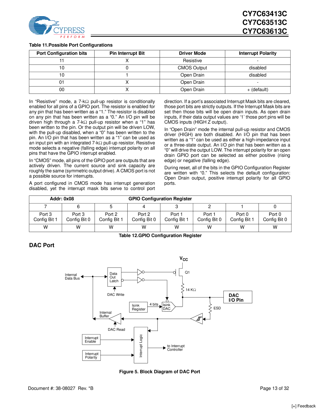
Figure 5. Block Diagram of DAC Port

Document #: 38-08027 Rev. *B

Page 13 of 32

[+] Feedback

Page 13
Image 13
Cypress CY7C63513C, CY7C63613C, CY7C63413C manual DAC Port, Cmos Output, + default, Addr Gpio Configuration Register

CY7C63613C, CY7C63413C, CY7C63513C specifications

The Cypress CY7C63513C, CY7C63413C, and CY7C63613C are versatile programmable logic devices that are part of the Cypress family of microcontrollers designed for diverse applications. These devices are particularly well-suited for embedded systems, consumer electronics, and industrial control systems due to their robust features and technologies.

One of the standout characteristics of these devices is their programmable architecture, which allows for flexible design implementations. The CY7C63513C features 32 programmable I/O pins and an 8-bit microcontroller core, which provides ample resource allocation for various input/output operations. The device supports various communication interfaces, including SPI and I2C, enabling seamless integration into different system configurations.

The CY7C63413C is a highly adaptable component, offering similar features but with an enhanced flexibility in its I/O configuration, making it ideal for applications that require quick prototyping and development cycles. Its extensive instruction set allows for more complex processing tasks, catering to advanced applications in automation and signal processing.

On the other hand, the CY7C63613C provides an advanced level of integration with built-in support for multiple power management modes. This feature is crucial in modern battery-operated devices where energy conservation is a primary concern. Its low-power operation enhances the usability in portable applications while still maintaining performance.

In terms of performance, all three devices boast high-speed operation, with clock frequencies reaching up to 24 MHz. This ensures that they can efficiently handle tasks that require real-time processing, such as sensor data management and control algorithms. The devices are also equipped with an on-chip EEPROM and RAM, allowing for data storage and quick retrieval.

In addition to their performance characteristics, the CY7C63513C, CY7C63413C, and CY7C63613C are designed with reliability in mind. They incorporate robust error detection and correction features, ensuring data integrity during operation. This reliability is essential for critical applications, such as automotive systems and industrial automation.

Overall, the Cypress CY7 series presents an appealing solution for developers looking for a blend of flexibility, performance, and reliability in their embedded designs. Their programmability and support for multiple communication protocols make them a formidable choice in today’s fast-paced technological landscape, paving the way for innovative applications across various industries.