CY7C68013A, CY7C68014A


CY7C68015A, CY7C68016A


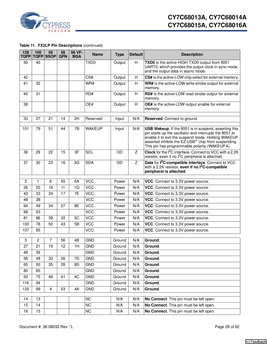
Table 11. FX2LP Pin Descriptions (continued)


128

100

56

56

56 VF-

Name

Type

Default

Description


TQFP

TQFP

SSOP

QFN

BGA


50

40


TXD0

Output

H

TXD0 is the active-HIGH TXD0 output from 8051


UART0, which provides the output clock in sync mode,


and the output data in async mode.


42


CS#

Output

H

CS# is the active-LOW chip select for external memory.


41

32


WR#

Output

H

WR# is the active-LOW write strobe output for external


memory.


40

31


RD#

Output

H

RD# is the active-LOW read strobe output for external


memory.


38


OE#

Output

H

OE# is the active-LOW output enable for external


memory.


33

27

21

14

2H

Reserved

Input

N/A

Reserved. Connect to ground.


101

79

51

44

7B

WAKEUP

Input

N/A

USB Wakeup. If the 8051 is in suspend, asserting this


pin starts up the oscillator and interrupts the 8051 to


enable it to exit the suspend mode. Holding WAKEUP


asserted inhibits the EZ-USBchip from suspending.


This pin has programmable polarity (WAKEUP.4).


36

29

22

15

3F

SCL

OD

Z

Clock for the I2C interface. Connect to VCC with a 2.2K


resistor, even if no I2C peripheral is attached.


37

30

23

16

3G

SDA

OD

Z

Data for I2C-compatible interface. Connect to VCC


with a 2.2K resistor, even if no I2C-compatible


peripheral is attached.


2

1

6

55

5A

VCC

Power

N/A

VCC. Connect to 3.3V power source.


26

20

18

11

1G

VCC

Power

N/A

VCC. Connect to 3.3V power source.


43

33

24

17

7E

VCC

Power

N/A

VCC. Connect to 3.3V power source.


48

38


VCC

Power

N/A

VCC. Connect to 3.3V power source.


64

49

34

27

8E

VCC

Power

N/A

VCC. Connect to 3.3V power source.


68

53


VCC

Power

N/A

VCC. Connect to 3.3V power source.


81

66

39

32

5C

VCC

Power

N/A

VCC. Connect to 3.3V power source.


100

78

50

43

5B

VCC

Power

N/A

VCC. Connect to 3.3V power source.


107

85


VCC

Power

N/A

VCC. Connect to 3.3V power source.


3

2

7

56

4B

GND

Ground

N/A

Ground.


27

21

19

12

1H

GND

Ground

N/A

Ground.


49

39


GND

Ground

N/A

Ground.


58

48

33

26

7D

GND

Ground

N/A

Ground.


65

50

35

28

8D

GND

Ground

N/A

Ground.


80

65


GND

Ground

N/A

Ground.


93

75

48

41

4C

GND

Ground

N/A

Ground.


116

94


GND

Ground

N/A

Ground.


125

99

4

53

4A

GND

Ground

N/A

Ground.


14

13


NC

N/A

N/A

No Connect. This pin must be left open.


15

14


NC

N/A

N/A

No Connect. This pin must be left open.


16

15


NC

N/A

N/A

No Connect. This pin must be left open.


Document #: 38-08032 Rev. *L


Page 28 of 62

[+] Feedback

Page 28
Image 28
Cypress CY7C68013, CY7C68015A, CY7C68016A, CY7C68014A manual Ground

CY7C68016A, CY7C68014A, CY7C68015A, CY7C68013 specifications

The Cypress CY7C68013, CY7C68015A, CY7C68014A, and CY7C68016A are part of Cypress Semiconductor's EZ-USB family of microcontrollers, known for their high performance and flexibility in USB applications. These devices are primarily used for USB interfacing and have gained popularity in various industries due to their robust features and capabilities.

One of the main features of the CY7C68013 is its Dual FIFO architecture, allowing for efficient data transfer between USB and the system memory. This feature optimizes throughput and reduces CPU overhead, making it an excellent choice for applications that require high-speed data exchange, such as video streaming, data acquisition, and industrial automation. The device is equipped with a USB 2.0 interface which supports full-speed operation at 12 Mbps, ensuring compatibility with a wide range of USB devices.

The CY7C68015A, a similar variant, offers additional memory options, providing users with the flexibility to select the necessary capacity for their specific applications. This part is particularly useful in scenarios that demand more users or higher data storage, making it ideal for complex USB peripherals like printers and multifunction devices. Moreover, it includes a unique capability of upgradeable firmware, ensuring that the device remains relevant and functional as technology evolves.

In contrast, the CY7C68014A stands out with its support for isochronous data transfers, making it suitable for real-time applications that require timely data delivery. This is particularly important in audio and video applications where delays can impact performance. The device incorporates advanced power management features, allowing it to operate efficiently both in low and high-power modes.

Lastly, the CY7C68016A integrates enhanced security features, positioning it as an ideal choice for applications that require data integrity and protection against unauthorized access. It supports various encryption standards and provides secure boot capabilities, making it suitable for secure environments such as financial transactions and sensitive data processing.

In summary, the CY7C68013, CY7C68015A, CY7C68014A, and CY7C68016A microcontrollers offer a versatile suite of features that cater to a wide array of USB applications. Their design emphasizes performance, flexibility, and security, making them essential components in today's rapidly evolving technology landscape. Whether in consumer electronics, industrial automation, or specialized applications, these devices provide the reliability and efficiency that engineers and developers require.