CY8C23433, CY8C23533
Debugger
The PSoC Designer Debugger subsystem provides hardware
Online Help System
The online help system displays online,
Hardware Tools
In-Circuit Emulator
A low cost, high functionality ICE
The emulator consists of a base unit that connects to the PC by way of a USB port. The base unit is universal and can operate with all PSoC devices. Emulation pods for each device family are available separately. The emulation pod takes the place of the PSoC device in the target board and performs full speed (24 MHz) operation.
Designing with User Modules
The development process for the PSoC device differs from that of a traditional fixed function microprocessor. The configurable analog and digital hardware blocks give the PSoC architecture a unique flexibility that pays dividends in managing specification change during development and by lowering inventory costs. These configurable resources, called PSoC Blocks, have the ability to implement a wide variety of
To speed the development process, the PSoC Designer Integrated Development Environment (IDE) provides a library of
Each user module establishes the basic register settings that implement the selected function. It also provides parameters that allow you to tailor its precise configuration to your particular application. For example, a Pulse Width Modulator User Module configures one or more digital PSoC blocks, one for each 8 bits
of resolution. The user module parameters permit you to establish the pulse width and duty cycle. User modules also provide tested software to cut your development time. The user module application programming interface (API) provides high level functions to control and respond to hardware events at
The API functions are documented in user module data sheets that are viewed directly in the PSoC Designer IDE. These data sheets explain the internal operation of the user module and provide performance specifications. Each data sheet describes the use of each user module parameter and documents the setting of each register controlled by the user module.
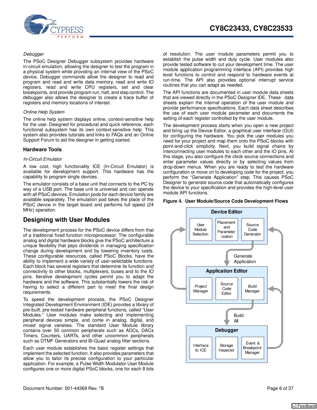
The development process starts when you open a new project and bring up the Device Editor, a graphical user interface (GUI) for configuring the hardware. You pick the user modules you need for your project and map them onto the PSoC blocks with
Figure 4. User Module/Source Code Development Flows
|
|
|
| Device Editor |
|
|
|
|
|
|
|
| |||||||
|
|
|
|
|
|
|
|
|
|
|
|
|
|
|
|
|
|
| |
|
|
| User |
|
| Placement |
|
|
| Source |
|
|
| ||||||
|
|
|
|
| and |
|
|
|
|
|
| ||||||||
|
|
| Module |
|
|
|
|
| Code |
|
|
| |||||||
|
|
|
|
| Parameter |
|
|
|
|
|
| ||||||||
|
|
|
|
|
|
|
|
|
| ||||||||||
|
|
| Selection |
|
|
|
|
| Generator |
|
|
| |||||||
|
|
|
|
|
|
|
|
|
|
| |||||||||
|
|
|
|
|
|
|
|
|
|
|
|
|
|
|
| ||||
|
|
|
|
|
|
|
|
|
|
|
|
|
|
|
| ||||
|
|
|
|
|
|
|
|
|
|
|
|
|
|
|
|
|
|
|
|
|
|
|
|
|
|
|
|
|
|
|
| ||||||||
|
|
|
|
|
|
|
|
|
|
|
|
| |||||||
|
|
|
|
|
|
|
|
| Generate |
|
| ||||||||
|
|
|
|
|
|
|
|
|
|
| |||||||||
|
|
|
|
|
|
|
|
| Application |
|
| ||||||||
|
|
|
|
|
|
|
|
|
|
| |||||||||
|
|
|
|
|
|
|
|
|
|
|
|
|
|
|
| ||||
|
|
| Application Editor |
|
| ||||||||||||||
|
|
|
|
|
|
|
|
|
|
|
|
|
|
|
|
|
|
|
|
|
|
| Project |
|
| Source |
|
|
| Build |
|
|
| ||||||
|
|
|
|
| Code |
|
|
|
|
|
| ||||||||
|
|
| Manager |
|
|
|
|
| Manager |
|
|
| |||||||
|
|
|
|
|
|
|
| ||||||||||||
|
|
|
|
| Editor |
|
|
|
|
|
| ||||||||
|
|
|
|
|
|
|
|
|
|
|
|
|
|
|
| ||||
|
|
|
|
|
|
|
|
|
|
|
|
|
|
|
|
|
|
| |
|
|
|
|
|
|
|
|
|
|
|
|
|
|
|
|
|
|
|
|
|
|
|
|
|
|
|
|
|
|
|
|
|
|
|
|
| |||
|
|
|
|
|
|
|
|
|
|
|
|
|
|
|
|
| |||
|
|
|
|
|
|
|
|
| Build |
|
|
|
|
|
|
| |||
|
|
|
|
|
|
|
|
|
|
|
|
|
|
|
| ||||
|
|
|
|
|
|
|
|
| All |
|
|
|
|
|
|
|
| ||
|
|
|
|
|
|
|
|
|
|
|
|
|
|
|
|
| |||
|
|
|
|
|
|
|
|
|
|
|
|
|
|
|
|
|
|
|
|
|
|
|
|
| Debugger |
|
|
|
|
|
|
|
| ||||||
|
|
|
|
|
|
|
|
|
|
|
|
|
|
|
|
|
|
|
|
|
|
| Interface |
|
| Storage |
|
|
| Event & |
|
|
| ||||||
|
|
|
|
|
|
| Breakpoint |
|
|
| |||||||||
|
|
| to ICE |
|
| Inspector |
|
|
|
|
| ||||||||
|
|
|
|
|
|
|
|
|
| ||||||||||
|
|
|
|
|
|
|
| Manager |
|
|
| ||||||||
|
|
|
|
|
|
|
|
|
|
|
|
|
|
|
| ||||
|
|
|
|
|
|
|
|
|
|
|
|
|
|
|
|
|
|
|
|
|
|
|
|
|
|
|
|
|
|
|
|
|
|
|
|
|
|
|
|
Document Number: | Page 6 of 37 |
[+] Feedback