Front Panel
Place the Router in a location where the LED indicators can be easily viewed.
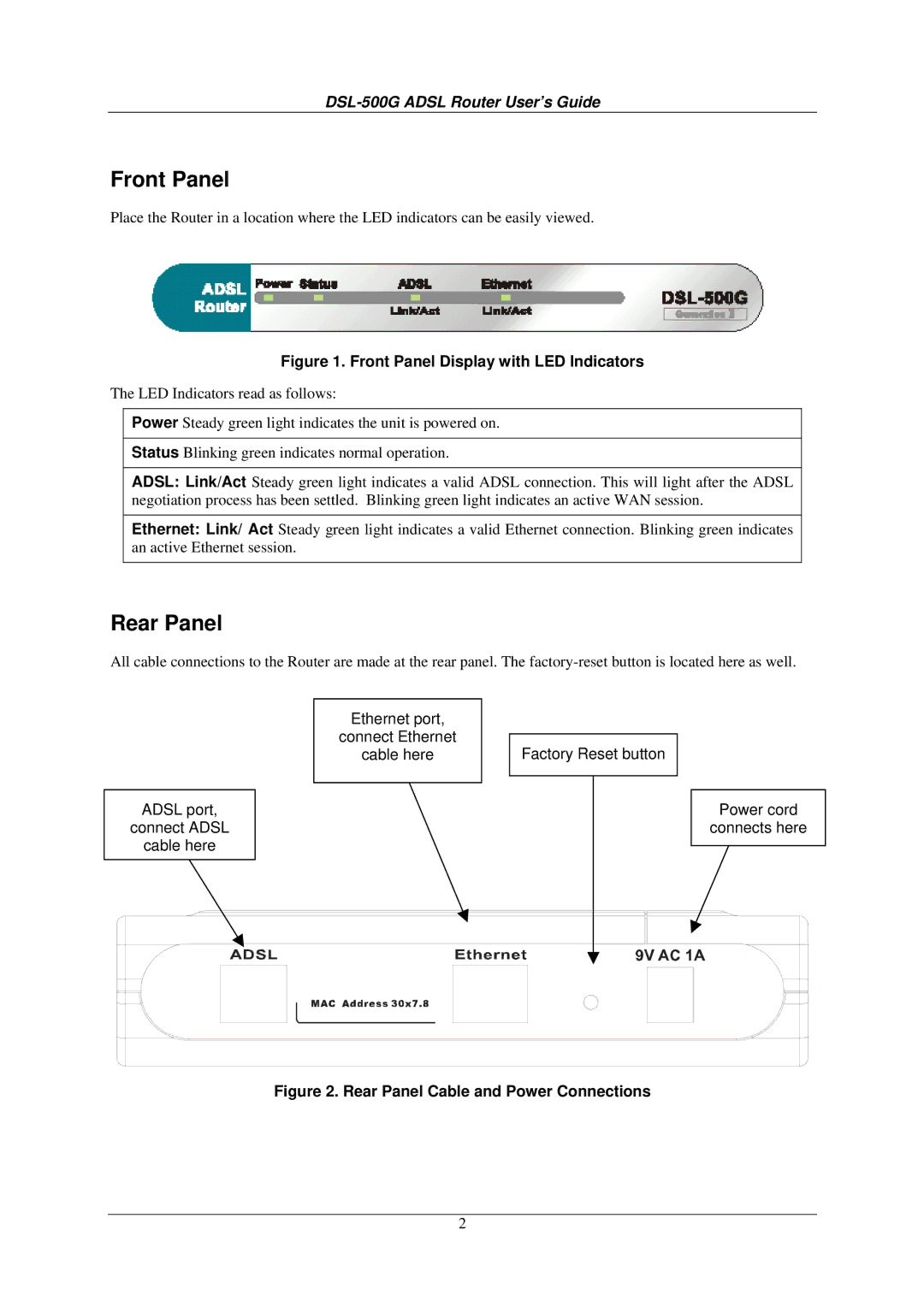
Figure 1. Front Panel Display with LED Indicators
The LED Indicators read as follows:
Power Steady green light indicates the unit is powered on.
Status Blinking green indicates normal operation.
ADSL: Link/Act Steady green light indicates a valid ADSL connection. This will light after the ADSL negotiation process has been settled. Blinking green light indicates an active WAN session.
Ethernet: Link/ Act Steady green light indicates a valid Ethernet connection. Blinking green indicates an active Ethernet session.
Rear Panel
All cable connections to the Router are made at the rear panel. The
ADSL port,
connect ADSL
cable here
Ethernet port,
connect Ethernet
cable here
Factory Reset button
Power cord
connects here
Figure 2. Rear Panel Cable and Power Connections
2