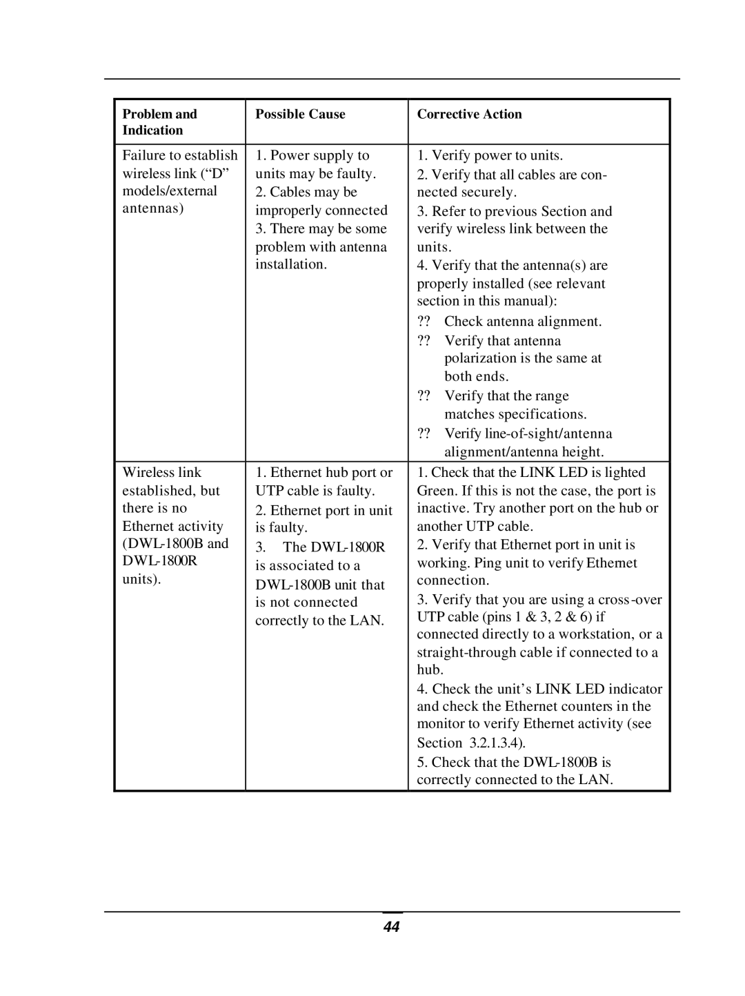
Problem and | Possible Cause | Corrective Action | |
Indication |
|
|
|
|
|
| |
Failure to establish | 1. Power supply to | 1. Verify power to units. | |
wireless link (“D” | units may be faulty. | 2. Verify that all cables are con- | |
models/external | 2. Cables may be | nected securely. | |
antennas) | improperly connected | 3. Refer to previous Section and | |
| 3. There may be some | verify wireless link between the | |
| problem with antenna | units. | |
| installation. | 4. Verify that the antenna(s) are | |
|
| properly installed (see relevant | |
|
| section in this manual): | |
|
| ?? | Check antenna alignment. |
|
| ?? | Verify that antenna |
|
|
| polarization is the same at |
|
|
| both ends. |
|
| ?? Verify that the range | |
|
|
| matches specifications. |
|
| ?? | Verify |
|
|
| alignment/antenna height. |
Wireless link | 1. Ethernet hub port or | 1. Check that the LINK LED is lighted | |
established, but | UTP cable is faulty. | Green. If this is not the case, the port is | |
there is no | 2. Ethernet port in unit | inactive. Try another port on the hub or | |
Ethernet activity | is faulty. | another UTP cable. | |
3. The | 2. Verify that Ethernet port in unit is | ||
is associated to a | working. Ping unit to verify Ethernet | ||
units). | connection. | ||
| 3. Verify that you are using a cross | ||
| is not connected | ||
| correctly to the LAN. | UTP cable (pins 1 & 3, 2 & 6) if | |
|
| connected directly to a workstation, or a | |
|
| ||
|
| hub. |
|
|
| 4. Check the unit’s LINK LED indicator | |
|
| and check the Ethernet counters in the | |
|
| monitor to verify Ethernet activity (see | |
|
| Section 3.2.1.3.4). | |
|
| 5. Check that the | |
|
| correctly connected to the LAN. | |
|
|
|
|
44
