Dip Switch 1 switches the MP 6000 between simple GPI control and RS 232 control. If Dip Switch 1 is Off (up) the MP 6000 responds to GPI, if it is On (down) then it responds to RS 232. The Front Panel and the GPI interface will be deactivated if RS 232 control is selected
DIP switch
DIP switch 1 OFF (up),
• GPI trigger is enabled.
Dip Switches
DIP switch 1 ON (When this function is turned on, the front panel and GPI function will be disabled. Only “EJECT” will work.)
•External RS 232 device control enabled.
DIP switch 2 OFF (up)
•GPI function is set to momentary closure (Pulse Trigger).
GPI Port
DIP switch 2 ON
•GPI function is set to maintained closure (Level Trigger).
Note: Please make sure the MP 6000 is turned off before changing DIP switch settings.
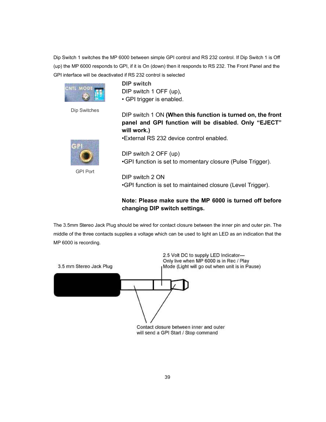
The 3.5mm Stereo Jack Plug should be wired for contact closure between the inner pin and outer pin. The middle of the three contacts supplies a voltage which can be used to light an LED as an indication that the MP 6000 is recording.
39