3If an emergency
4Plug the equipment to be protected into the UPS output receptacles, but do not turn on the protected equipment.
NOTE: Verify that the total equipment ratings do not exceed the UPS capacity to prevent an overload alarm.
Installing Remote Emergency Power-off
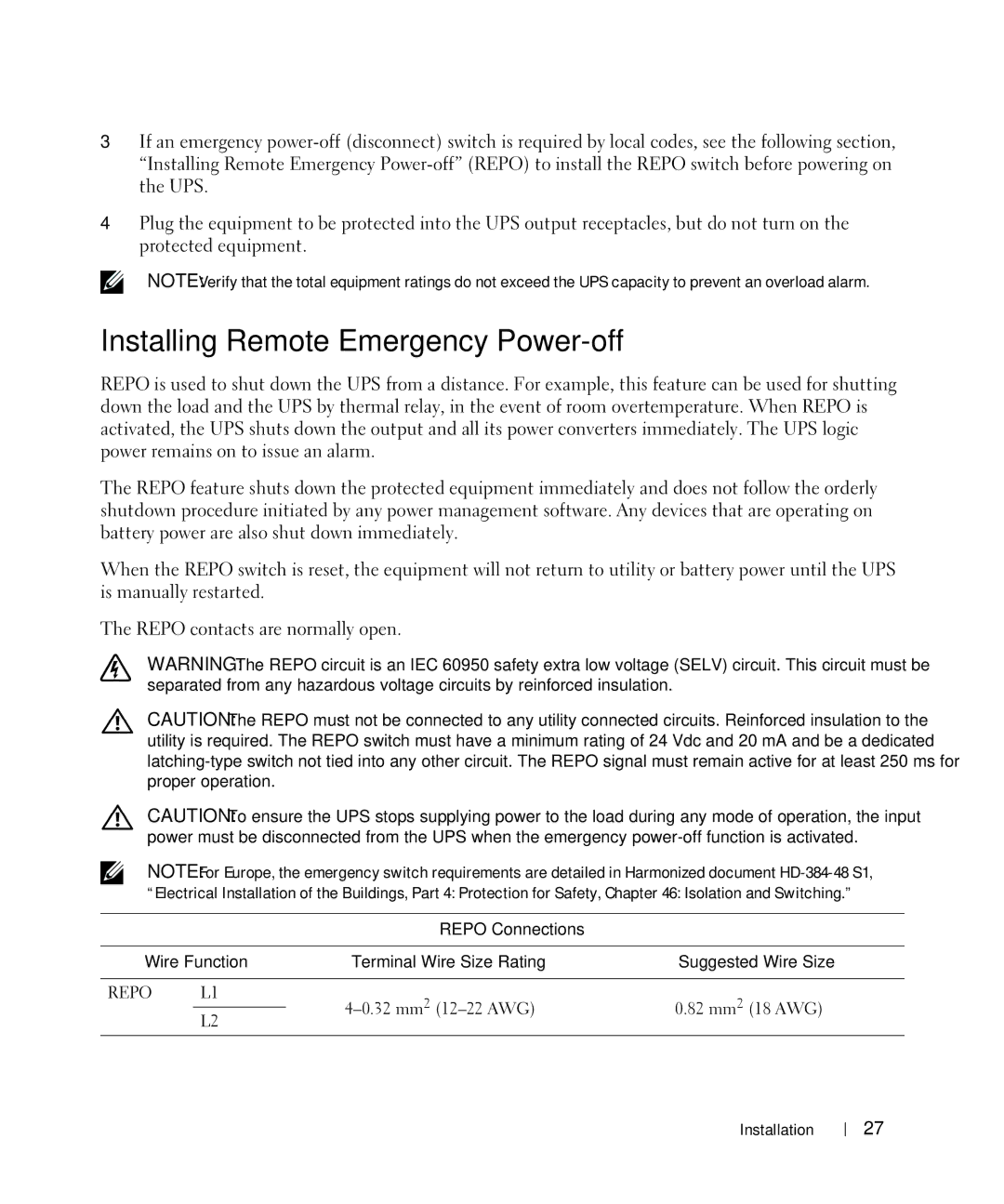
REPO is used to shut down the UPS from a distance. For example, this feature can be used for shutting down the load and the UPS by thermal relay, in the event of room overtemperature. When REPO is activated, the UPS shuts down the output and all its power converters immediately. The UPS logic power remains on to issue an alarm.
The REPO feature shuts down the protected equipment immediately and does not follow the orderly shutdown procedure initiated by any power management software. Any devices that are operating on battery power are also shut down immediately.
When the REPO switch is reset, the equipment will not return to utility or battery power until the UPS is manually restarted.
The REPO contacts are normally open.
WARNING: The REPO circuit is an IEC 60950 safety extra low voltage (SELV) circuit. This circuit must be separated from any hazardous voltage circuits by reinforced insulation.
CAUTION: The REPO must not be connected to any utility connected circuits. Reinforced insulation to the utility is required. The REPO switch must have a minimum rating of 24 Vdc and 20 mA and be a dedicated
CAUTION: To ensure the UPS stops supplying power to the load during any mode of operation, the input power must be disconnected from the UPS when the emergency
NOTE: For Europe, the emergency switch requirements are detailed in Harmonized document
“Electrical Installation of the Buildings, Part 4: Protection for Safety, Chapter 46: Isolation and Switching.”
REPO Connections
Wire Function | Terminal Wire Size Rating | Suggested Wire Size | |
|
|
|
|
REPO | L1 | 0.82 mm2 (18 AWG) | |
|
| ||
| L2 | ||
|
|
| |
|
|
|
|
Installation 27
