NOTE: The pins must be open to keep the UPS running. If the UPS shuts down because the REPO connector pins are shorted, restart the UPS by
NOTE: Always test the REPO function before applying your critical load to avoid accidental load loss.
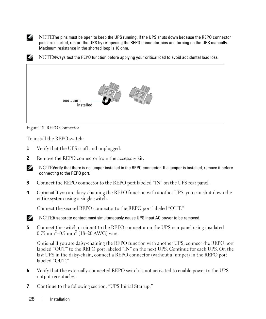
Remove Jumper if |
installed |
Figure 18. REPO Connector
To install the REPO switch:
1Verify that the UPS is off and unplugged.
2Remove the REPO connector from the accessory kit.
NOTE: Verify that there is no jumper installed in the REPO connector. If a jumper is installed, remove it before connecting to the REPO port.
3Connect the REPO connector to the REPO port labeled “IN” on the UPS rear panel.
4Optional. If you are
Connect the second REPO connector to the REPO port labeled “OUT.”
NOTE: A separate contact must simultaneously cause UPS input AC power to be removed.
5Connect the switch or circuit to the REPO connector on the UPS rear panel using insulated 0.75
Optional. If you are
6Verify that the
7Continue to the following section, “UPS Initial Startup.”
28 Installation