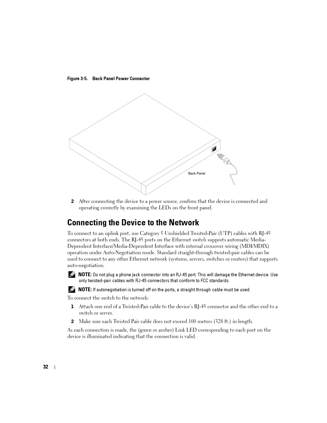
Figure 3-5. Back Panel Power Connector
2After connecting the device to a power source, confirm that the device is connected and operating correctly by examining the LEDs on the front panel.
Connecting the Device to the Network
To connect to an uplink port, use Category 5 Unshielded
NOTE: Do not plug a phone jack connector into an
NOTE: If autonegotiation is turned off on the ports, a straight through cable must be used.
To connect the switch to the network:
1Attach one end of a
2Make sure each Twisted Pair cable does not exceed 100 meters (328 ft.) in length.
As each connection is made, the (green or amber) Link LED corresponding to each port on the device is illuminated indicating that the connection is valid.
32