Delta Electronics DVPCOPM-SL manual Sending SDO, NMT and Reading Emergency by Ladder Diagram

Models: DVPCOPM-SL

1 32
Download 32 pages 6.11 Kb
Page 22
Image 22
5 Sending SDO, NMT and Reading Emergency by Ladder Diagram

CANopen Communication Module DVPCOPM-SL

zProgram explanations:

1.The first 3 rows of the program set up the communication format between DVP-SA and IFD9503, which is 115,200bps, 7E1-ASCII; communication port is COM2.

2.When M0 = On, send the input status of X20 ~ X28 on DVP-08ST to D256, and send the data in b0 ~ b15 of D0 to M10 ~ M25.

3.When D0 = 1, M10 will be On, and Y0 on DVP-SA MPU will output.

5 Sending SDO, NMT and Reading Emergency by Ladder Diagram

5.1The Principle

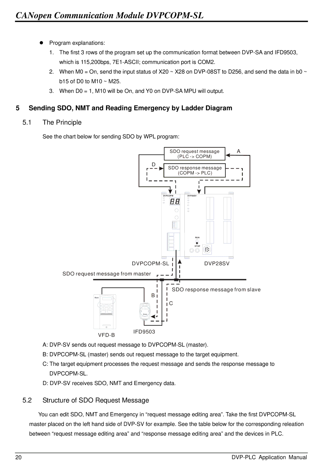
See the chart below for sending SDO by WPL program:

D

SDO request message

A

(PLC -> COPM)


SDO response message

(COPM -> PLC)

DVPCOPMDVP28SV

RUN

STOP

DVPCOPM-SL

SDO request message from master

DVP28SV

B 5.1The Principle

VFD-BIFD9503

SDO response message from slave

C

A:DVP-SV sends out request message to DVPCOPM-SL (master).

B:DVPCOPM-SL (master) sends out request message to the target equipment.

C:The target equipment processes the request message and sends the response message to

DVPCOPM-SL.

D:DVP-SV receives SDO, NMT and Emergency data.

5.2Structure of SDO Request Message

You can edit SDO, NMT and Emergency in “request message editing area”. Take the first DVPCOPM-SL master placed on the left hand side of DVP-SV for example. See the table below for the corresponding releation between “request message editing area” and “response message editing area” and the devices in PLC.

20

DVP-PLC Application Manual

Page 22
Image 22
Delta Electronics DVPCOPM-SL manual Sending SDO, NMT and Reading Emergency by Ladder Diagram, The Principle