CANopen Communication Module
Note:
zUse slotted screwdriver to adjust the DIP switch carefully in case you scratch the switch.
zPlease set up the function switch when the power is switched off. After the setup is completed,
2.6Digital Indicator
The digital indicator provides the following two functions:
zDisplaying the node address of
zDisplaying the error message of slave.
3 Basic Operation
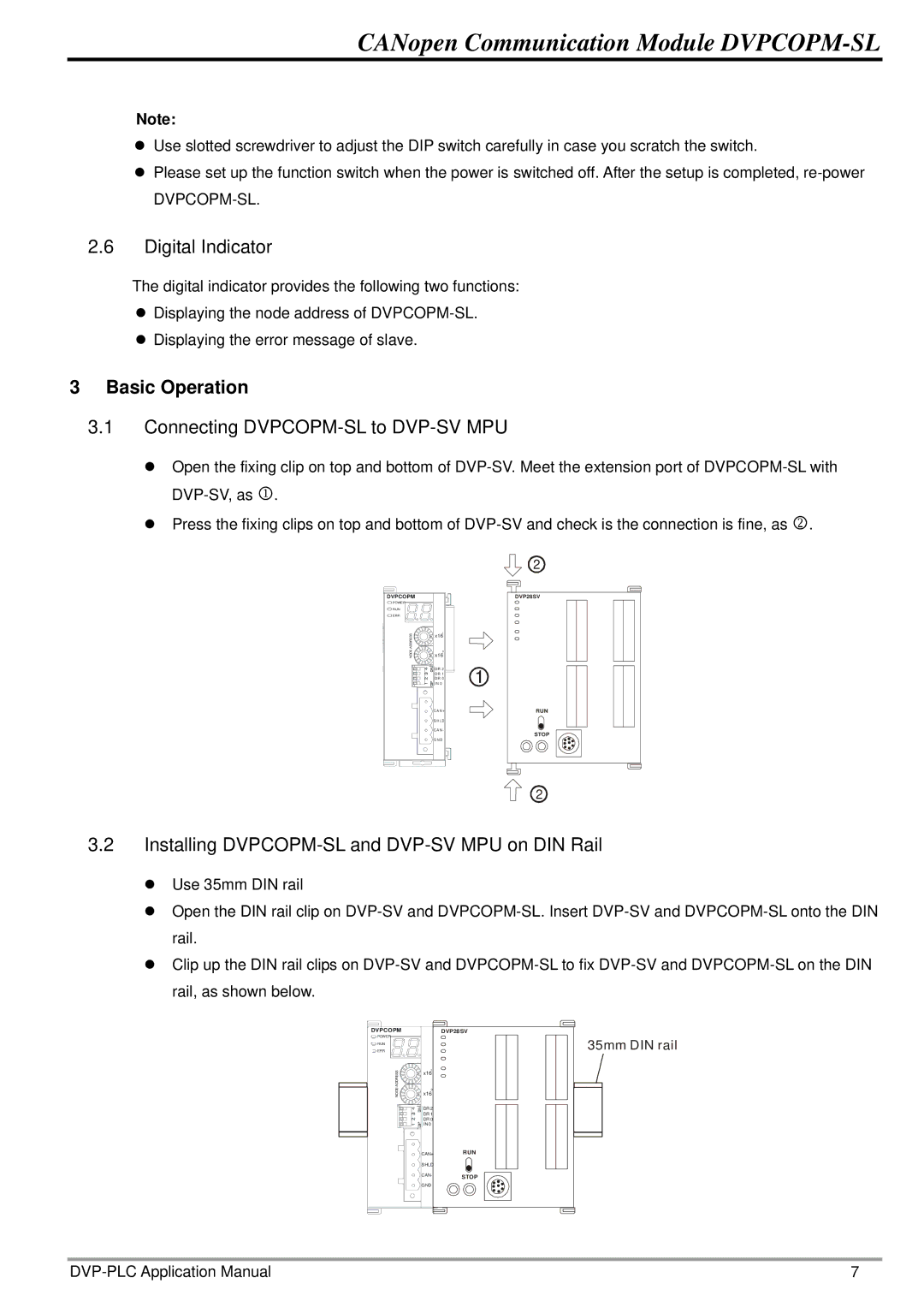
3.1Connecting DVPCOPM-SL to DVP-SV MPU
zOpen the fixing clip on top and bottom of
zPress the fixing clips on top and bottom of
DVPCOPM
![]() POWE R
POWE R
RUN
ERR
ADDRESS | 1 | |
x16 | ||
x16 | ||
NODE | ||
| 0 | |
| D R 2 | |
| D R 1 | |
| D R 0 | |
| I N 0 | |
| C A N + | |
| S H LD | |
| C A N - | |
| G N D |
DVP28SV
1
RUN
STOP
2
3.2Installing DVPCOPM-SL and DVP-SV MPU on DIN Rail
zUse 35mm DIN rail
zOpen the DIN rail clip on
zClip up the DIN rail clips on
DVPCOPM
POWER
![]() RUN
RUN
ERR
ADDRESS | 1 | |
x16 | ||
| ||
NODE | x16 | |
| 0 | |
| DR 2 | |
| DR 1 | |
| DR 0 | |
| IN 0 | |
| CAN+ | |
| SHLD | |
| CAN- | |
| GND |
DVP28SV
RUN
STOP
35mm DIN rail
7 |
