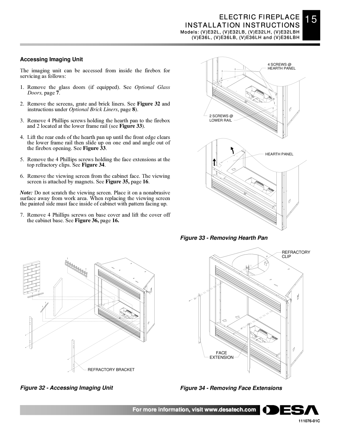
E32, VE36, VE32, E36(L)(B)(H) specifications
Desa E32, VE36, VE32, and E36 represent a series of innovative models designed to meet the diverse needs of contemporary consumers. These products combine cutting-edge technology with practical features, creating a user-friendly experience that appeals to both residential and commercial applications.The Desa E32 stands out for its energy efficiency and robust design, making it an ideal choice for those seeking sustainable solutions. Its exterior is built from high-quality materials, ensuring durability and resistance to wear over time. This model boasts advanced insulation technology, minimizing heat loss and enhancing performance. The E32 is equipped with a smart thermostat that allows users to program temperature settings according to their preferences, ensuring optimal comfort throughout the day.
The VE36, on the other hand, is engineered for versatility. Its sleek design and compact size make it suitable for various environments, including homes, offices, and even recreational spaces. This model features an intuitive digital interface that allows for easy operation and monitoring. With multiple heating modes and a quick heat-up time, the VE36 can adapt to any situation, providing immediate warmth when needed.
Next in line is the VE32, which emphasizes both efficiency and safety. It features an advanced safety shut-off mechanism, ensuring peace of mind for users. This model utilizes innovative heating technology to deliver consistent warmth while consuming minimal energy. The VE32 also includes a self-cleaning function, making maintenance hassle-free and increasing the lifespan of the unit.
Lastly, the E36(L)(B)(H) model offers modular designs that can be customized to suit specific needs. This multi-faceted unit can adjust its output based on the space it is heating, optimizing performance while reducing energy consumption. The inclusion of smart connectivity features allows users to control the device remotely via smartphone applications, enhancing convenience and adaptability.
In summary, Desa E32, VE36, VE32, and E36(L)(B)(H) models showcase a commitment to quality, efficiency, and user comfort. With their technological advancements, robust safety features, and stylish designs, these models are well-equipped to elevate any space while addressing modern heating challenges. Their ability to adapt to various settings makes them a valuable addition to any home or business environment.

